FMCW radar sensor for motor vehicles

a technology for fmcw radar and motor vehicles, applied in the direction of instruments, measurement devices, using reradiation, etc., can solve the problems of inability to meet the needs of stationary objects in all situations, the accuracy of wheel-speed sensors tends to worsen, and the calibration error of certain parameters, etc., to achieve the effect of simple and precise manner

Active Publication Date: 2021-02-09
ROBERT BOSCH GMBH
View PDF9 Cites 0 Cited by
  • Summary
  • Abstract
  • Description
  • Claims
  • Application Information

AI Technical Summary

Benefits of technology

[0011]It is an object of the present invention to provide an FMCW radar sensor that makes it possible to determine the ego speed of the vehicle in a simple and precise manner.
[0013]Since the radar lobe of an FMCW radar sensor has a certain extension in elevation, it includes both radar beams that are directed obliquely to the road surface, and radar beams that are directed obliquely in the upward direction and away from the road surface, and as a limit case, it also includes radar beams that propagate parallel to the road surface. This may offer the possibility of carrying out a measurement of the ego velocity at the limit α=0, provided the velocity resolution of the radar sensor is adequate. According to the present invention, the high velocity resolution may be achieved by using special modulation sequences that have a particularly long duration and a particularly low frequency swing. In the extreme case, the frequency swing is equal to zero so that it involves a pure Doppler sequence, so that only the relative velocity is measured and no distance measurement takes place. Due to the greater duration, and thus the longer measuring time of these modulation sequences, the precision of the relative velocity measurement is considerably improved. This makes it possible to measure the relative velocities of the radar targets created by surface irregularities of the road in a highly accurate manner.
[0014]In this context it is advantageous that to the extent that angle α approaches the limit value of zero, the radar lobe sweeps an ever larger distance range at the road surface; on the other hand, since the cosine function at α=0 has a gradient of zero, the measured Doppler frequencies differ less and less from one another. As a whole, this may lead to a considerable increase in the signal density until the signal finally abruptly drops at the Doppler frequency that corresponds to the ego velocity of the vehicle. This effect is even amplified in that the radar lobe also sweeps an ever larger portion of the road surface in the width direction with increasing distance, while the azimuth angles of the radar beams lie close to zero (in relation to the longitudinal vehicle axis). A cosine function describes the dependency of the relative velocity from the azimuth angle also for the targets that lie beyond the longitudinal vehicle axis, so that in an accumulation of the signal across a specific azimuth angle region, an even stronger signal accumulation and an increase in the signal density occur, which allows for an even clearer detection of the abrupt drop in the signal strength at α=0.

Problems solved by technology

Although the ego velocity may in principle be determined with the aid of the signals from wheel-speed sensors that are part of an ESP system, these measurements always include a certain calibration error because the exact wheel diameter is not known.
In addition, with decreasing rotational speed, the accuracy of the wheel-speed sensors tends to worsen.
However, it is disadvantageous that suitable stationary objects are not available in all situations.

Method used


Image

  • FMCW radar sensor for motor vehicles
  • FMCW radar sensor for motor vehicles
  • FMCW radar sensor for motor vehicles

Examples


Embodiment Construction

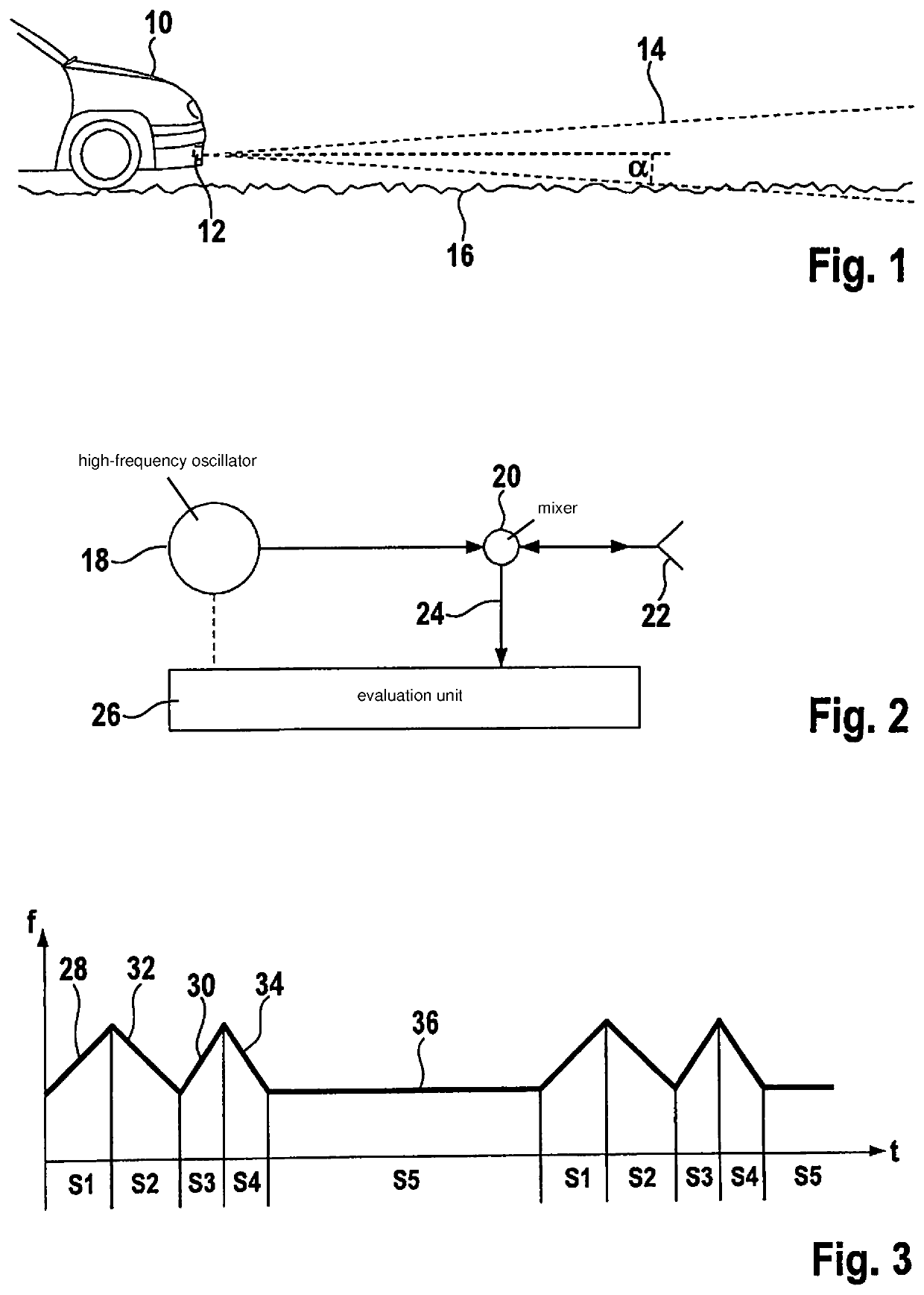
[0023]FIG. 1 shows a front part of a motor vehicle 10, which has an FMCW radar sensor 12 installed behind the bumper. The radar sensor emits a radar lobe 14, which is directed toward the front in the direction of travel of vehicle 10 and, in elevation, is aligned approximately parallel to a road surface 16 depicted in exaggerated form in this instance. Since the radar lobe diverges both in azimuth and in elevation, a portion of the radar beams impinges upon road surface 16 starting at a certain distance in front of vehicle 10. The small surface irregularities on the road surface form targets by which a radar echo is returned to the radar sensor. These radar echoes generated by road surface 16, which are known as ground clutter, are utilized according to the present invention for measuring the ego velocity of vehicle 10. In addition, it is of course also possible to evaluate radar echoes from other stationary objects, e.g., radar echoes from roadside structures adjacent to the road.

[...


PUM


Abstract

An FMWC radar sensor for motor vehicles, having a high-frequency oscillator, which is developed to generate a frequency-modulated transmit signal that has a periodically repeating series of modulation sequences having different modulation patterns, and having an evaluation device for evaluating the received radar echo according to the FMCW principle, wherein the series of the modulation sequences includes a special class of modulation sequences whose duration is longer than that of any other modulation sequence not belonging to this class and whose frequency swing is smaller than that of any other modulation sequence, and the evaluation device is developed to carry out a measurement of the ego velocity of the vehicle on the basis of a radar echo that is received from non-moving objects during the modulation sequences that belong to the special class.

Description

CROSS REFERENCE[0001]The present application claims the benefit under 35 U.S.C. § 119 of German Patent Application No. DE 102017209628.4 filed on Jun. 8, 2017, which is expressly incorporated herein by reference in its entirety.FIELD[0002]The present invention relates to an FMCW radar sensor for motor vehicles, which has a high-frequency oscillator designed to generate a frequency-modulated sensor signal that has a periodically repeating series of modulation sequences having different modulation patterns; it also has an evaluation device for evaluating the received radar echo according to the FMCW principle.BACKGROUND INFORMATION[0003]FMCW radar sensors are used in motor vehicles mainly for measuring distances and relative velocities of vehicles driving ahead. For this reason, the radar sensor is typically installed in the front of the vehicle and emits the radar beams essentially in the longitudinal direction of the vehicle. The radar beam has only a limited opening angle in azimut...

Claims


Application Information

Patent Timeline
Patent Type & Authority Patents(United States)
IPC IPC(8): G01S13/58G01S13/60G01S13/32G01S13/34G01S7/35G01S7/03G01S13/536G01S13/931
CPCG01S13/584G01S7/03G01S7/35G01S7/354G01S13/32G01S13/345G01S13/536G01S13/60G01S13/931G01S13/605G01S2013/932G01S2013/93271
Inventor BUDDENDICK, HERMANNSCHLOSSER, MARKUS
Owner ROBERT BOSCH GMBH
Why Eureka
Try Eureka