Method of controlling an inductive heating circuit to seal a packaging material

a technology of inductive heating circuit and packaging material, which is applied in the field of induction heating, can solve the problems of insufficient accuracy to obtain high power efficiency, affect the load in it is difficult to obtain a power delivery that is capable of following the dynamics of the inductive heating circuit, so as to improve the scalability and reduce the amount of tim

Active Publication Date: 2021-02-16
TETRA LAVAL HLDG & FINANCE SA
View PDF6 Cites 3 Cited by
  • Summary
  • Abstract
  • Description
  • Claims
  • Application Information

AI Technical Summary

Benefits of technology

[0011]Some examples of the disclosure provide for increased efficiency of the power delivery in an induction heating circuit.
[0026]Some examples of the disclosure provide for improving the scalability of an inductive heating circuit in a filling machine with increased number of simultaneous welding applications.

Problems solved by technology

A problem arising in previous solutions is that the intermediate transformer matching network, between the power generator and the inductors, is not accurate enough to obtain high power efficiency when several different inductors are present in the application chain.
Induction heating with the purpose of sealing packaging materials has the added difficulties that the transformation of the material from the initial state to a heated and welded or sealed state affects the load in the inductive heating circuit, since the packaging material is magnetically coupled to the inductor, via the electrically conducting component of the laminate.
Adding the complexity of having a plurality of inductors, each presenting a unique characteristic and state in the application process, it is difficult to obtain a power delivery that is capable of following the dynamics of the inductive heating circuit.
The lack of accuracy and efficiency, resulting in part from the variation of the load in the inductive heating circuit, will limit the throughput, which is detrimental in high-speed applications.
Further, in order to limit these effects, the deficiencies of the induction heating circuit must be compensated, which will lead to a more complex design that could also limit the throughput or decrease the efficiency, in addition to increased costs.
Another consequence relating to reduced efficiency of the power delivery in the induction heating circuit is reduced lifetime of the components.

Method used


Image

  • Method of controlling an inductive heating circuit to seal a packaging material
  • Method of controlling an inductive heating circuit to seal a packaging material
  • Method of controlling an inductive heating circuit to seal a packaging material

Examples


Embodiment Construction

[0039]Specific embodiments of the invention will now be described with reference to the accompanying drawings. This invention may, however, be embodied in many different forms and should not be construed as limited to the embodiments set forth herein; rather, these embodiments are provided so that this disclosure will be thorough and complete, and will fully convey the scope of the invention to those skilled in the art. The terminology used in the detailed description of the embodiments illustrated in the accompanying drawings is not intended to be limiting of the invention. In the drawings, like numbers refer to like elements.

[0040]The following description focuses on examples applicable to inductive heating for sealing packaging containers. However, it will be appreciated that the examples are not limited to this application but may be applied to controlling inductive heating in many other applications.

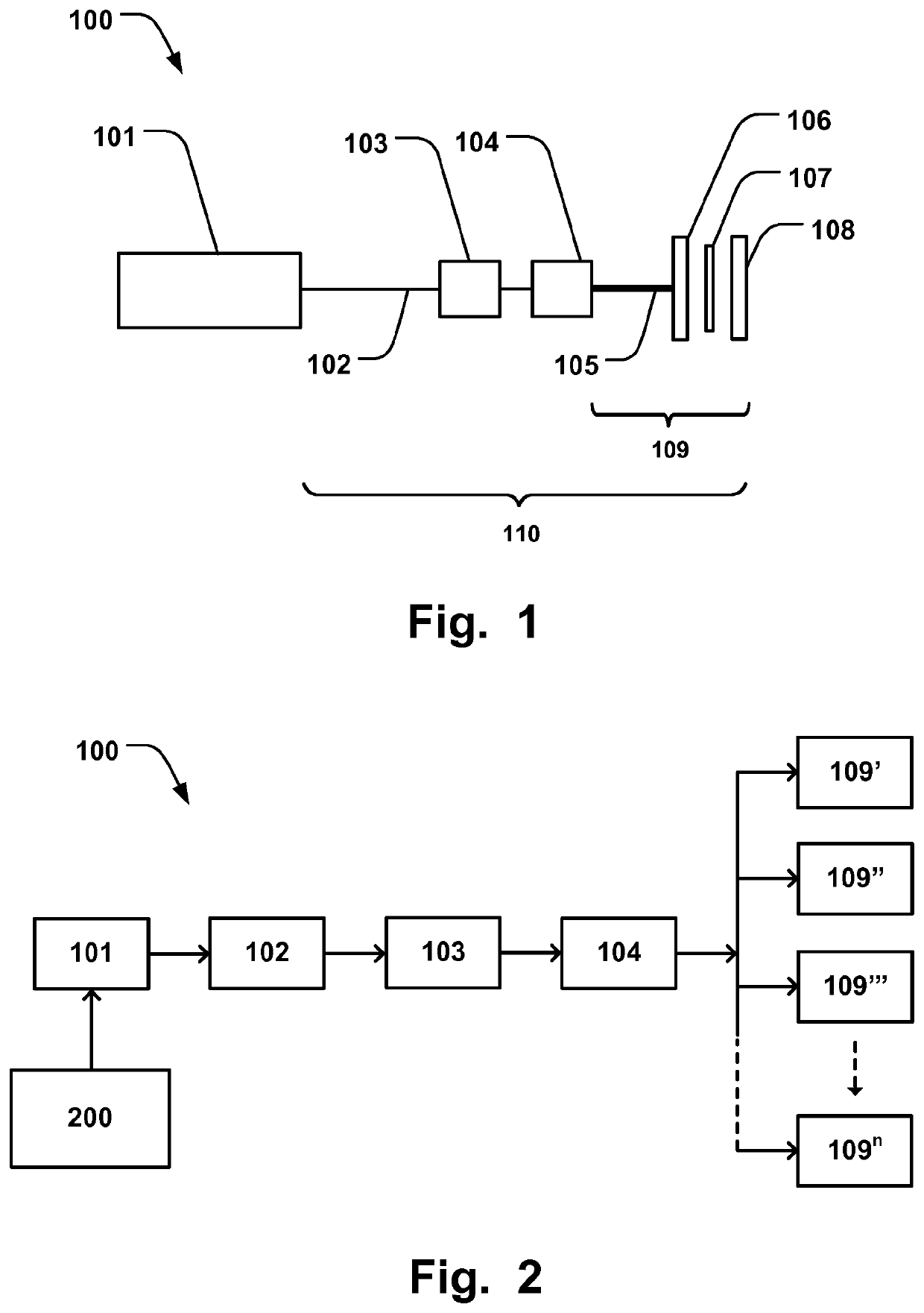
[0041]FIG. 1 shows an inductive heating circuit 100, in which an induction powe...


PUM

PropertyMeasurementUnit
resistanceaaaaaaaaaa
impedanceaaaaaaaaaa
frequencyaaaaaaaaaa

Abstract

A method of controlling an inductive heating circuit, having a varying load, to seal a packaging material is provided. The method comprises generating AC power of at least two frequencies on at least one inductor in the inductive heating circuit; determining of the resulting phase shift in the inductive heating circuit from the current generated at the at least two frequencies; determining the impedance of the inductive heating circuit for each of the at least two frequencies; determining a load characteristics of the inductive heating circuit based on the relationship between the determined impedance and the determined phase shift; determining an impedance operating range; and selecting an AC output frequency for an induction power generator based on the load characteristics which results in the least amount of phase shift from a set ideal value and which is associated with an impedance that is within the impedance operating range.

Description

FIELD OF THE INVENTION[0001]The present invention generally relates to the field of induction heating. More particularly, the present invention relates to a method of controlling an inductive heating circuit, having a varying load, to seal a packaging material, and a control device for controlling the induction heating circuit.BACKGROUND OF THE INVENTION[0002]The welding of laminated packing material by means of induction heat is used in the packaging industry. One example of such a laminated material is a carrier layer of paper, aluminium foil and thermoplastic coatings along the inner and outer surfaces of the laminate. The technique of induction welding is based on the fact that the magnetic field around a conductor, generated by an alternating current is capable of inducing a current in an adjoining electrically conducting material, which depending on the resistance of the material, warms up the material. Thus, in induction welding an inductor loop or coil provided against the l...

Claims


Application Information

Patent Timeline
Patent Type & Authority Patents(United States)
IPC IPC(8): B29C65/36B29C65/00H05B6/04H05B6/08H05B6/44B65B51/22B29L31/00B29K705/02
CPCB29C66/91311B29C65/3656B29C65/3668B29C66/849B29C66/91651B29C66/9512B29C66/9592B29C66/961B65B51/227H05B6/04H05B6/08H05B6/44B29K2705/02B29L2031/712H05B6/06B29C65/368B29C66/1122B29C66/4312B29C66/72321B29C66/83221
Inventor LANCELLOTTI, MIRCOGUERRI, ROSSANOBOSCHI, ALESSANDRO
Owner TETRA LAVAL HLDG & FINANCE SA
Why Eureka
Try Eureka