Method for projecting a beam of particles onto a substrate with correction of scattering effects

Active Publication Date: 2021-02-16
COMMISSARIAT A LENERGIE ATOMIQUE ET AUX ENERGIES ALTERNATIVES
View PDF6 Cites 0 Cited by
  • Summary
  • Abstract
  • Description
  • Claims
  • Application Information

AI Technical Summary

Benefits of technology

[0027]The invention aims to overcome the aforementioned drawbacks of the prior art. More precisely, it aims to provide an analytical expression of a PSF allowing a better correction of proximity

Problems solved by technology

The direct use of the dose profiles calculated by Monte-Carlo simulations to correct the proximity effects may yield, at least in principle, almost ideal results, but the computation time required is much too long for most practical applications.
None of these approaches has proved to be entirely satisf

Method used


Image

  • Method for projecting a beam of particles onto a substrate with correction of scattering effects
  • Method for projecting a beam of particles onto a substrate with correction of scattering effects
  • Method for projecting a beam of particles onto a substrate with correction of scattering effects

Examples


Example

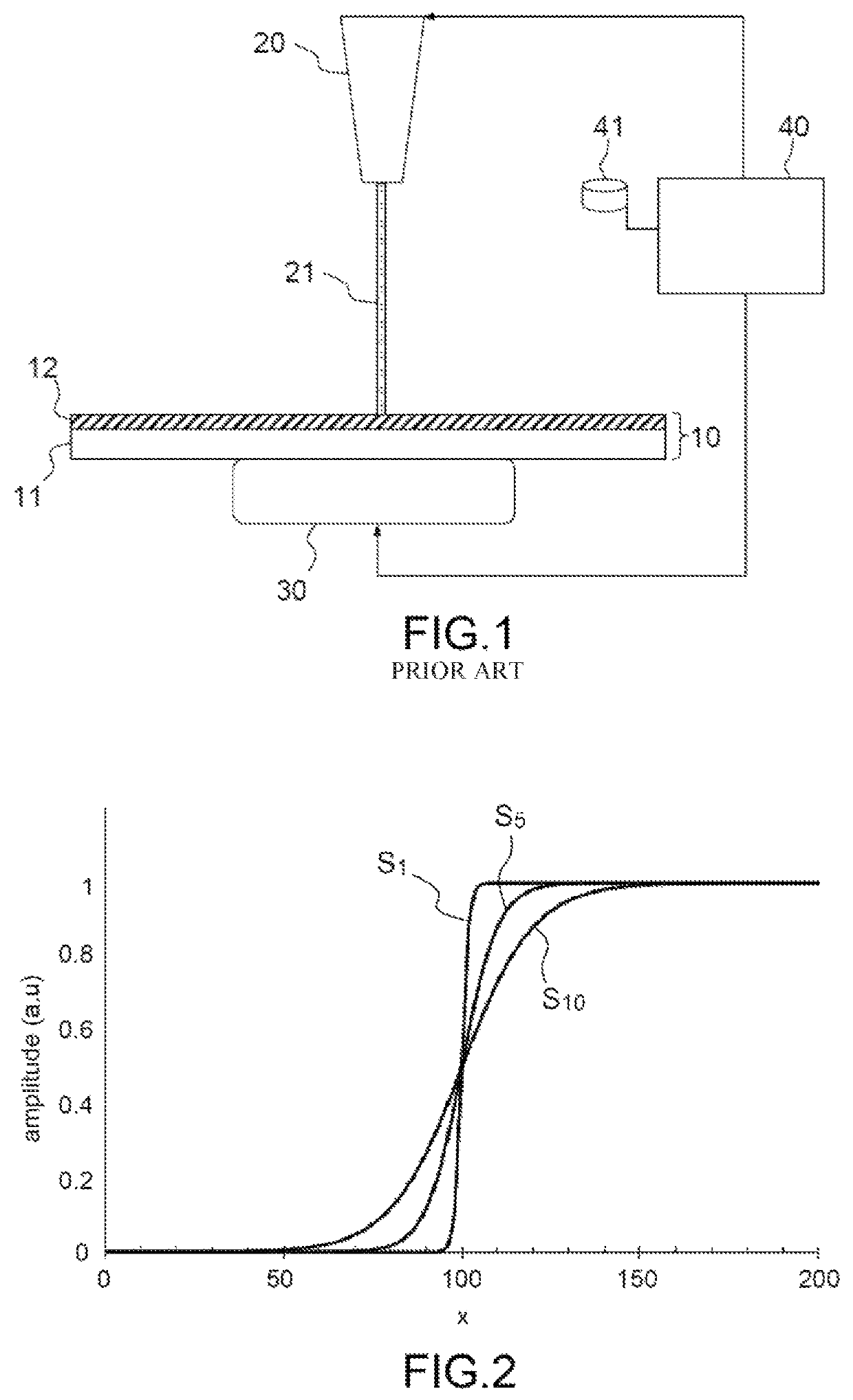
[0044]Generally, a sigmoid function is a function that has two horizontal asymptotes, which pass gradually from one to the other and that have an inflection point. In a more restricted sense, this term designates the function

[0045]S⁡(x)=11+e-(x-x0) / k(2)

which is also called the logistic function.

[0046]Function (2) depends on two parameters: x0, which determines the position of the inflection point, and k, which determines the steepness of the transition region between the two asymptotes (more precisely, 1 / k is the value of the derivative of S(x) at the inflection point x=x0). FIG. 2 shows graphs of three logistic curves with x0=100 and k=1 (curve S1), k=5 (curve S5) and k=10 (curve S10).

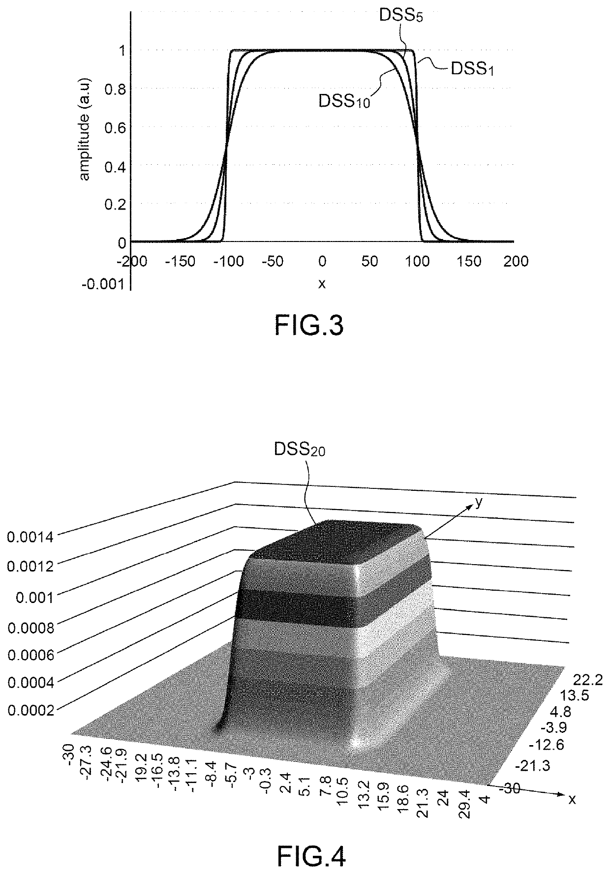
[0047]A double sigmoid function is given by the difference between two sigmoid functions of the type of equation (2). In particular, if the difference between two sigmoid functions having the same parameter k and parameters x0 of same absolute value but opposite sign is calculated, a function is obtai...


PUM


Abstract

A method for projecting a particle beam onto a substrate, the method includes a step of calculating a correction of the scattering effects of the beam by means of a point spread function modelling the forward scattering effects of the particles; a step of modifying a dose profile of the beam, implementing the correction thus calculated; and a step of projecting the beam, the dose profile of which has been modified, onto the substrate, and being wherein the point spread function is, or comprises by way of expression of a linear combination, a two-dimensional double sigmoid function. A method to e-beam lithography is also provided.

Description

CROSS-REFERENCE TO RELATED APPLICATIONS[0001]This application is a National Stage of International patent application PCT / EP2017 / 063657, filed on Jun. 6, 2017, which claims priority to foreign French patent application No. FR 1655610, filed on Jun. 16, 2016, the disclosures of which are incorporated by reference in their entirety.FIELD OF THE INVENTION[0002]The invention relates to a method for projecting a beam of particles, in particular of electrons, onto a substrate, and to a computer-program product for implementing such a method. It in particular applies to the field of e-beam lithography for direct etching on wafers or manufacture of masks, but also to e-beam microscopy and more generally to any field in which it is necessary to model and control the interaction of a beam of particles (electrons, but also ions, or even neutral atoms) with a target.BACKGROUND[0003]E-beam lithography (or electron-beam lithography) is the most widely used maskless—or “direct write”—lithography t...

Claims


Application Information

Patent Timeline
IPC IPC(8): G03F7/20H01J37/317G06F30/20G06F111/08
CPCH01J37/3175G03F7/2059G03F7/2061H01J37/3174G06F30/20G06F2111/08H01J2237/31754H01J2237/31769H01J2237/31776H01J2237/31777
Inventor CONSTANCIAS, CHRISTOPHE
Owner COMMISSARIAT A LENERGIE ATOMIQUE ET AUX ENERGIES ALTERNATIVES
Why Eureka
Try Eureka