Implantable cardiac stimulator with electrode-tissue interface characterization

Inactive Publication Date: 2007-04-03
CARDIAC PACEMAKERS INC
View PDF34 Cites 1 Cited by
  • Summary
  • Abstract
  • Description
  • Claims
  • Application Information

AI Technical Summary

Benefits of technology

[0025]In another embodiment, a single empirical estimate for the Helmholtz capacitance is substituted into the one part of the formula, either into the exponential term or into the additive and constant terms. The remaining term(s) may be reduced algebraically to solve for the unknown Helmholtz capacitance value. If the resulting calculation of the Helmholtz capacitance value does not agree with the originally substituted empirical estimate, then an updated empirical estimate is substituted into the first term(s), and

Problems solved by technology

However, when the body's natural pacemaker malfunctions, an implantable pacemaker often is required to properly stimulate the heart.
Moreover, pacemaker implementations range from the simple fixed rate, single chamber device that provides pacing with no sensing function, to highly complex models that provide fully automatic dual chamber pacing and sensing functions.
Although a purely resistive lead impedance estimate may provide a means for a rough estimate of pacer and battery condition, such an estimate may deviate significantly from the true impedance in some situations, since the physical and electrochemical properties that lead to the Helmholtz layer change with variations in the electric field intensity which develops at the electrode-electrolyte interface.
However, such estimates have neglected the reactive impedance component, as modeled by the Helmholtz capacitance, resulting in an incomplete cha

Method used


Image

  • Implantable cardiac stimulator with electrode-tissue interface characterization
  • Implantable cardiac stimulator with electrode-tissue interface characterization
  • Implantable cardiac stimulator with electrode-tissue interface characterization

Examples


Embodiment Construction

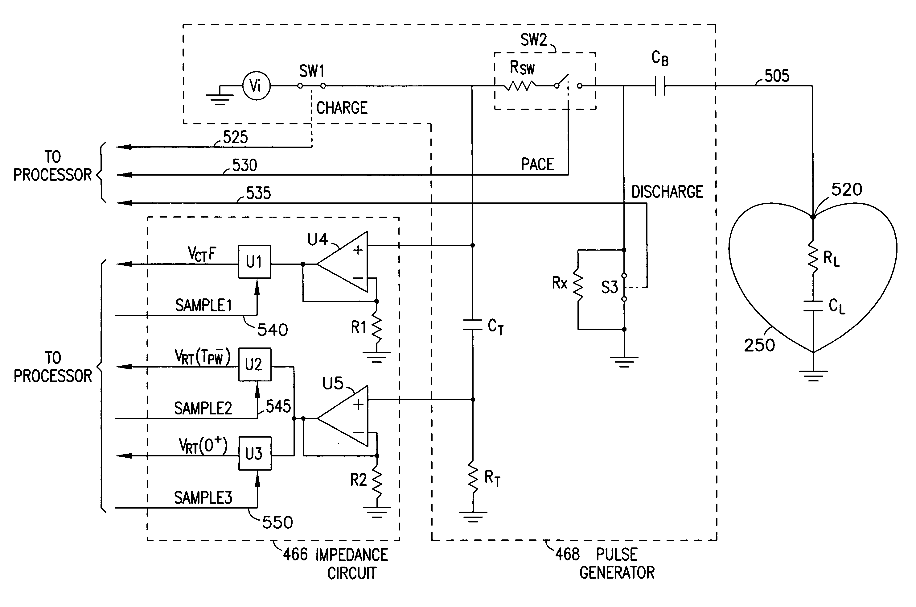
[0038]An exemplary cardiac stimulator 400 made in accordance with the present invention is illustrated in the block diagram of FIG. 4. The cardiac stimulator 400 may be a pacemaker, a defibrillator, or any or implantable cardiac stimulator. The cardiac stimulator 400 generally includes atrial and ventricular sense circuits 462 and 464, a processor 470, main memory 475, an impedance circuit 466, and a pulse generator 468, all housed in enclosure, or “can”401. The exemplary embodiment of FIG. 4 shows cardiac stimulator 400 with four leaded electrodes, namely atrial tip and ring electrodes 410 and 420, respectively, and ventricular ring and tip electrodes 440 and 450, respectively. Can 401 may function as an additional electrode in accordance with known techniques. The invention, however, may be practiced using any number of electrodes implanted in any chamber of the heart and in any configuration.

[0039]Referring still to FIG. 4, electrodes 410 and 420 couple to the atrial sense circui...


PUM


Abstract

A cardiac stimulator for measuring pacing impedance includes a tank capacitor for delivering charge to the heart via leads, a shunt resistor, and high-impedance buffers for measuring pacing current through the shunt resistor. During the stimulation pulse, the voltage across the shunt resistor, as sampled by a high-impedance buffer, variously indicates lead and cardiac tissue resistance or capacitance. A high-impedance buffer measures the voltage between the tank capacitor and ground immediately following the stimulation pulse to allow estimation of the lead/heart tissue capacitance. A lead/heart tissue capacitance estimate is determined by look-up table is in memory or successive approximation. When the lead/heart tissue capacitance and lead resistance have been determined, a plurality of parameters for analyzing and optimizing a cardiac stimulation system may be calculated, such as the instantaneous current, the average current, the charge, and the energy delivered to the cardiac tissue.

Description

CROSS-REFERENCE TO RELATED APPLICATION(S)[0001]This application is a division of U.S. patent application Ser. No. 10 / 371,609, filed on Feb. 21, 2003 now U.S. Pat. No. 6,788,972, which is a division of U.S. patent application Ser. No. 09 / 454,742, filed on Dec. 6, 1999, now issued as U.S. Pat. No. 6,564,099, which is a division of U.S. patent application Ser. No. 09 / 075,144, filed on May 8, 1998, now issued as U.S. Pat. No. 6,141,585, the specifications of which are incorporated by reference herein.[0002]Applicant further references U.S. patent application Ser. No. 09 / 454,619, filed on Dec. 6, 1999, now issued as U.S. Pat. No. 6,473,648, which is a division of U.S. patent application Ser. No. 09 / 075,144, filed on May 8, 1998, now issued as U.S. Pat. No. 6,141,585.FIELD OF THE INVENTION[0003]The present invention relates generally to implantable cardiac pacing systems and particularly to an improved technique for electrode-tissue interface characterization. More particularly, the prese...

Claims


Application Information

Patent Timeline
IPC IPC(8): A61N1/37A61M5/142A61M5/168A61N1/08A61N1/365
CPCA61M5/142A61M5/16854A61N1/36521A61N1/3706A61M5/14244A61N2001/083
Inventor PRUTCHI, DAVIDPAUL, PATRICK J.MARTIN, GREGORY R.
Owner CARDIAC PACEMAKERS INC
Why Eureka
Try Eureka