Heating device and heating chamber

a heating device and heating chamber technology, applied in lighting and heating apparatus, furnaces, charge manipulation, etc., can solve the problems of lowering production efficiency, unable to meet the requirements of fast heating and cooling, and the heat loss of heating light tubes, so as to reduce heat loss and improve heating efficiency. , the effect of fast heating

Active Publication Date: 2021-03-02
BEIJING NAURA MICROELECTRONICS EQUIP CO LTD
View PDF35 Cites 1 Cited by
  • Summary
  • Abstract
  • Description
  • Claims
  • Application Information

AI Technical Summary

Benefits of technology

[0047]The heating device provided by the present disclosure may reduce the heat loss of the heating light tube by using the heating light tube disposed below the to-be-heated member to directly radiate heat upwards and using the thermal radiation shielding assembly to shield heat radiated by the heating light tube towards the surroundings and bottom, thereby improving the heating efficiency. Further, the requirements of the high temperature PVD process on fast heating, high temperature preservation and fast cooling of a substrate may be satisfied. Further, the heating device provided by the present disclosure may not only be applied to a vacuum environment or an atmospheric environment directly, but may have a relatively large application range. Further, the heat loss of the heating tube in the vacuum environment may be less, thereby further improving the heating efficiency.
[0048]By using the aforementioned heating device, the heating chamber provided by the present disclosure not only has a relatively high heating efficiency, but may also be applied to a vacuum environment or an atmospheric environment, thereby expanding the application range.

Problems solved by technology

The following issues inevitably exist in the practical application of the electrical resistance heater.
First, the heating efficiency of the electrical resistance heater is relatively low, and the temperature of the substrate rises slowly, thereby lowering the production efficiency.
Thus, the existing electrical resistance heater fails to meet the requirement of fast heating and cooling for the high temperature PVD process.
Second, because the thermocouple acquires the temperature of the substrate indirectly by measuring the temperature of the base, and a difference (the difference is at least 100° C.) in temperature exists between the base and the substrate due to factors such as the thermal conduction efficiency, the accuracy of the temperature control of the substrate is relatively low.
In practical applications, the aforementioned heating device inevitably has the following issues.
For example, such heating method may not be applied to a magnetron sputtering chamber having a target material at the top thereof.
Second, because the heating bulbs 12 can only be used in an atmospheric environment, the heat loss is relatively high, which is particularly significant when high temperature heating (above 500° C.) is performed.
Accordingly, the heating efficiency is relatively low and high-temperature heating cannot be maintained.
Further, the heating bulbs 12 have to heat the substrate 14 indirectly via the sealed quartz window 13, resulting in heat loss.
Such step further reduces the heating efficiency.

Method used


Image

  • Heating device and heating chamber
  • Heating device and heating chamber
  • Heating device and heating chamber

Examples


Embodiment Construction

lass="d_n">[0062]To make the objects, technical solutions and advantages of the present disclosure clearer, a heating device and a heating chamber provided by the present disclosure will be described below in conjunction with the accompanying drawings. It should be understood that, specific embodiments described herein are merely used for explaining the present disclosure, rather than limiting the present disclosure.

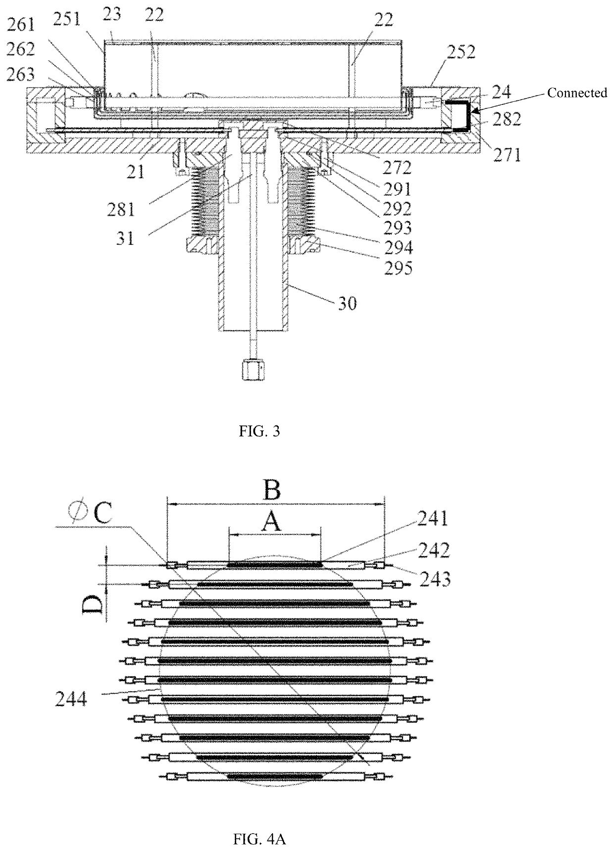
[0063]FIG. 3 is a cross-sectional view of a heating device provided by embodiments of the present disclosure. Referring to FIG. 3, the heating device is configured to heat a to-be-heated member 23 using a thermal radiation manner. The to-be-heated member 23 may be a single substrate or a tray for bearing a plurality of substrates. The heating device includes a base plate 21, three supporting columns 22, and a heating assembly. The three supporting columns 22 are arranged vertically on the base plate 21 and are distributed at intervals along the circumferential direction ...


PUM

PropertyMeasurementUnit
temperatureaaaaaaaaaa
temperature detectoraaaaaaaaaa

Abstract

A heating device and a heating chamber are provided, comprising a base plate (21), at least three supporting columns (22) and a heating assembly, where the at least three supporting columns are arranged vertically on the base plate and are distributed at intervals along a circumferential direction of the base plate Top ends of the at least three supporting columns form a bearing surface for supporting a to-be-heated member (23). The heating assembly includes a heating light tube (24) and a thermal radiation shielding assembly, where the heating light tube is disposed above the base plate and below the bearing surface. A projection of an effective heating area formed by uniform distribution of the heating light tube on the base plate covers a projection of the bearing surface on the base plate. The thermal radiation shielding assembly shields heat radiated by the heating light tube towards surroundings and bottom.

Description

CROSS-REFERENCE TO RELATED APPLICATIONS[0001]This application is a national phase entry under 35 U.S.C. § 371 of International Application No. PCT / CN2015 / 099858, filed on Dec. 30, 2015, which claims priority to and benefits of Chinese Patent Application Serial No. 201510648731.1, filed with the State Intellectual Property Office of P. R. China on Oct. 9, 2015, and claims priority to and benefits of Chinese Patent Application Serial No. 201510923022.X, filed with the State Intellectual Property Office of P.R. China on Dec. 10, 2015, the entire content of all of which is incorporated herein by reference.FIELD OF THE DISCLOSURE[0002]The present disclosure relates to the technical field of semiconductor device processing and, more particularly, relates to a heating device and a heating chamber.BACKGROUND[0003]As a common processing technology in the semiconductor field, the physical vapor deposition (PVD) technology such as a magnetron sputtering process is often performed in a vacuum c...

Claims


Application Information

Patent Timeline
Patent Type & Authority Patents(United States)
IPC IPC(8): H01L21/67C23C14/54H05B1/02H05B3/00F27D19/00F27D5/00C23C14/35F27D3/00H01L21/687
CPCH01L21/67115C23C14/541F27D5/0037H01L21/67248H05B1/0233H05B3/0047C23C14/35F27D2003/0065F27D2019/0003H01L21/67103H01L21/68792C23C14/22
Inventor ZHANG, JUNWU, XUEWEIDONG, BOYUXU, BAOGANGZHANG, HENANGUO, BINGLIANGZHANG, WENLIU, SHAOHUI
Owner BEIJING NAURA MICROELECTRONICS EQUIP CO LTD
Why Eureka
Try Eureka