
Tunable magnetic sphincter augmentation device

a sphincter and magnetic technology, applied in the field of sphincter augmentation devices, can solve problems such as the enlargement of the effective circumference of the loop, and achieve the effects of reducing the magnetic strength of the magnet, and first magnetic strength

Active Publication Date: 2021-03-16
CILAG GMBH INT +1
View PDF16 Cites 0 Cited by
  • Summary
  • Abstract
  • Description
  • Claims
  • Application Information

AI Technical Summary

Benefits of technology

The device effectively prevents reflux while allowing for easy passage of food and vomit by adjusting its circumference, reducing dysphagia and maintaining sphincter function, thereby addressing the limitations of existing devices.

Problems solved by technology

The reduction of the magnetic strength of the magnets results in enlargement of an effective circumference of the loop.

Method used


Image

  • Tunable magnetic sphincter augmentation device
  • Tunable magnetic sphincter augmentation device
  • Tunable magnetic sphincter augmentation device

Examples


example 1

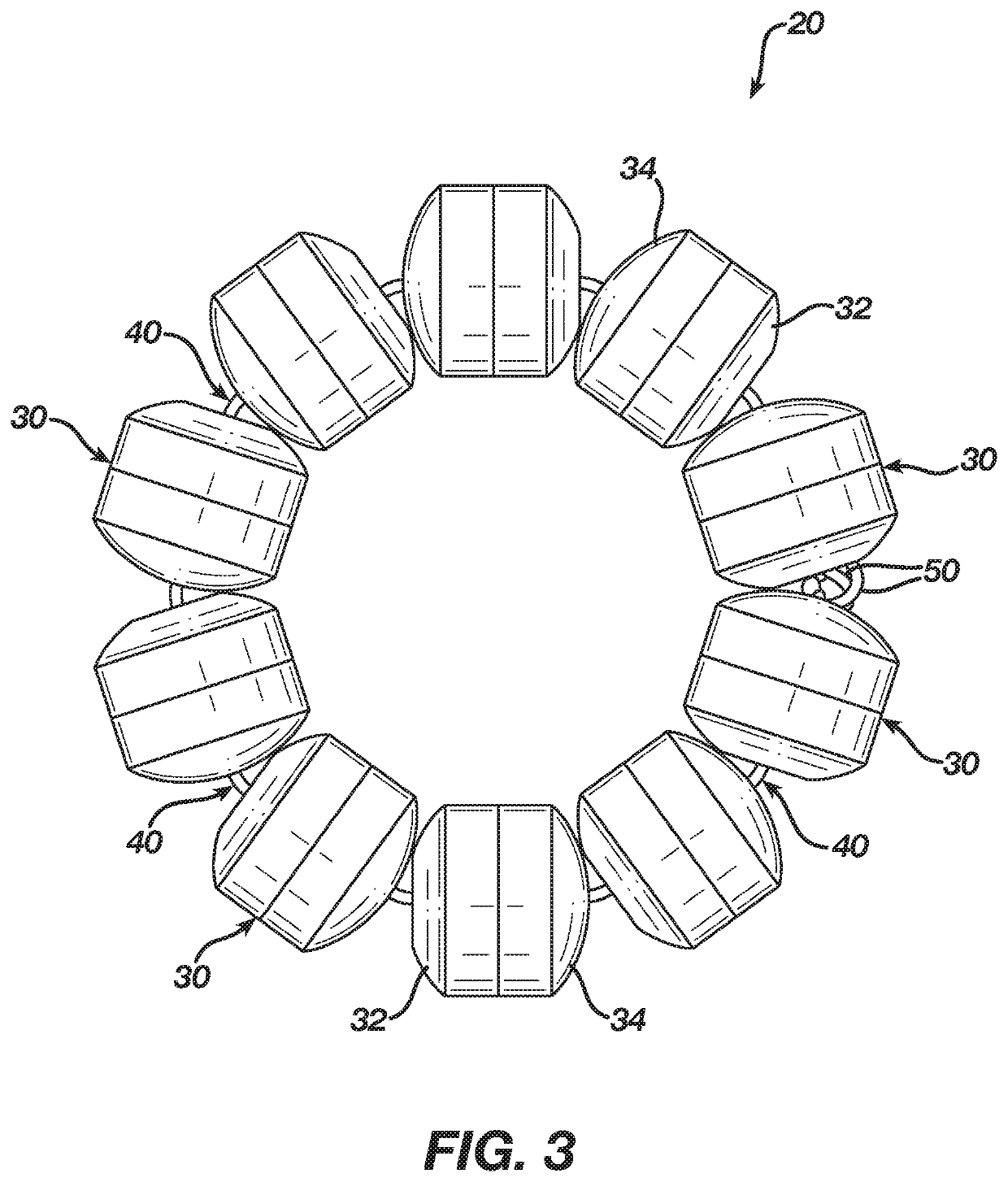
[0073]An apparatus, the apparatus comprising: (a) a plurality of beads, wherein each bead comprises: (i) a housing, (ii) a passageway extending through the housing, and (iii) at least one annular magnet, wherein the at least one annular magnet is coaxially positioned about the passageway; (b) a plurality of links joining the beads together, wherein portions of the links are slidably disposed in corresponding passageways of the beads; (c) a clasp assembly, wherein the clasp assembly is configured to removably secure the beads and links in a loop formation; and (d) an adjustment feature, wherein the adjustment feature is operable to adjust an effective circumference of the loop formation.

example 2

[0074]The apparatus of Example 1, further comprising a clasp link joining the clasp assembly with one of the beads.

example 3

[0075]The apparatus of Example 2, wherein the adjustment member is located in the clasp assembly, wherein the adjustment member comprises a clamping feature operable to selectively clamp the clasp link and thereby grip the clasp link.


PUM


Abstract

An apparatus includes a plurality of beads, a plurality of links, a clasp assembly, and an adjustment feature. Each bead includes a housing, a passageway extending through the housing, and at least one annular magnet. The at least one annular magnet is coaxially positioned about the passageway. The links join the beads together. Portions of the links are slidably disposed in corresponding passageways of the beads. The clasp assembly is configured to removably secure the beads and links in a loop formation. The adjustment feature is operable to adjust an effective circumference of the loop formation. The adjustment feature may be incorporated into one or both of the clasp assembly or at least one of the beads.

Description

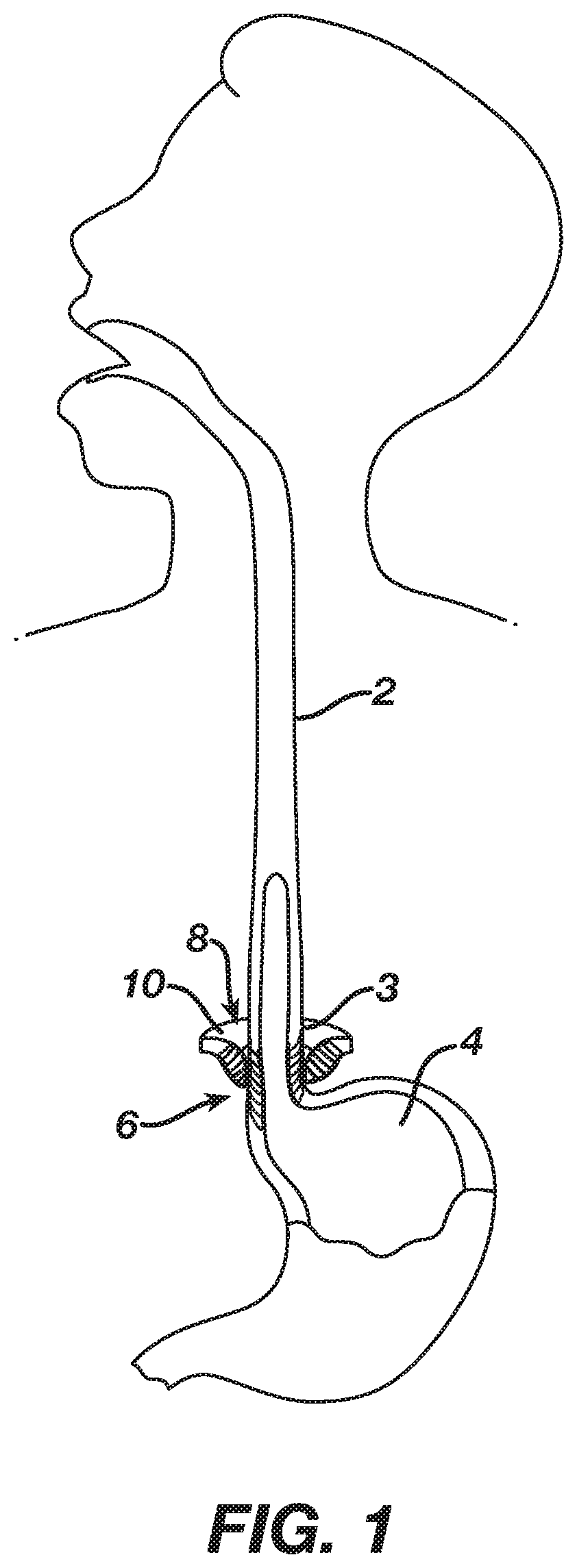
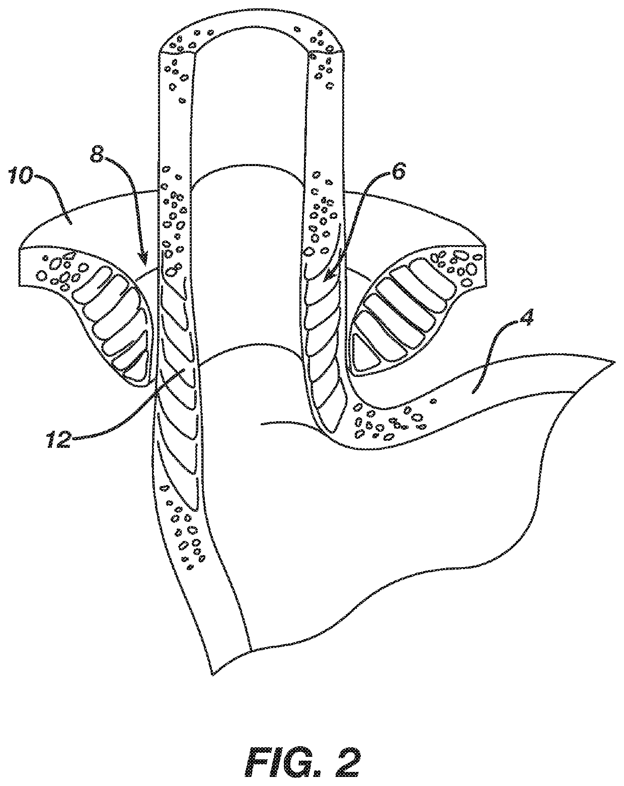
FIELD OF THE INVENTION[0001]The invention pertains to a sphincter augmentation device. More specifically, the invention pertains to a sphincter augmentation device that may be adjusted to vary a restrictive force imposed by the device on an anatomical structure.BACKGROUND[0002]In some instances, it may be desirable to place a medical implant within or surrounding a biological lumen / passageway in order to improve or assist the function of, or otherwise affect, the biological lumen / passageway. Examples of such biological lumens / passageways include, but are not limited to, the esophagus, a fallopian tube, a urethra, or a blood vessel. Some biological passages normally function by expanding and contracting actively or passively to regulate the flow of solids, liquids, gasses, or a combination thereof. The ability of a biological passage to expand and contract may be compromised by defects or disease. One merely illustrative example of a condition associated with decreased functionality ...

Claims


Application Information

Patent Timeline
Patent Type & Authority Patents(United States)
IPC IPC(8): A61B17/12A61F5/00A61B17/00A61F2/04A61B5/055
CPCA61B17/12013A61B17/12009A61F5/0079A61B5/055A61B2017/00477A61B2017/00827A61B2017/00876A61F2002/044
Inventor AULD, MICHAEL D.FLAKNE, LAUREN E.TAYLOR, KYLE P.GRUDEM, JR., JEROME K.HUSTER, CELESTE L.
Owner CILAG GMBH INT
Learn More