Control unit, device and method for the production of a three-dimensional object

a three-dimensional object and control unit technology, applied in the direction of additive manufacturing processes, manufacturing tools, turbines, etc., can solve the problems of reducing negative effect on the application of the subsequent layer, and reducing the effect of disruptive particles extracted by suction, so as to improve the effect of extracting disruptive particles by suction and improve the quality of the completed object. , the effect of simplifying the operation of the devi

Active Publication Date: 2021-03-16
EOS ELECTRO OPTICAL SYST
View PDF19 Cites 2 Cited by
  • Summary
  • Abstract
  • Description
  • Claims
  • Application Information

AI Technical Summary

Benefits of technology

[0010]The object of the present invention is therefore to provide an improved device and an improved method of producing a three-dimensional object. In particular, the effect of extracting disruptive particles by suction is preferably to be improved. Such an improvement can consist, for example, in that larger and heavier particles, produced during the solidifying of the build-up material, can also be reliably extracted by suction, whereby the quality of the completed object can be improved or the operation of the device simplified. A further improvement can also consist in that a more efficient effect of extraction by suction of disruptive particles is also achieved in the case of large building areas and / or at areas of the interior of the device more distant from the building area.

Problems solved by technology

These can have a disruptive effect on the production process, e.g. through disrupting the propagation of the laser beam, being precipitated on the coupling-in window for the laser beam or becoming deposited on or in the surface of the powder layer facing the laser beam and forming disruptive inclusions when solidifying of subsequent object positions which reduce the quality of the completed object or have a negative effect on the application of the subsequent layer.
When applying and solidifying a subsequent powder layer, such particles form disruptive inclusions which reduce the quality of the completed object.
It can also happen that particles of the aforementioned type, for example, become deposited in other areas of the interior of laser sintering devices and that these contaminants impair the operation of the laser device over time.

Method used


Image

  • Control unit, device and method for the production of a three-dimensional object
  • Control unit, device and method for the production of a three-dimensional object
  • Control unit, device and method for the production of a three-dimensional object

Examples


first embodiment

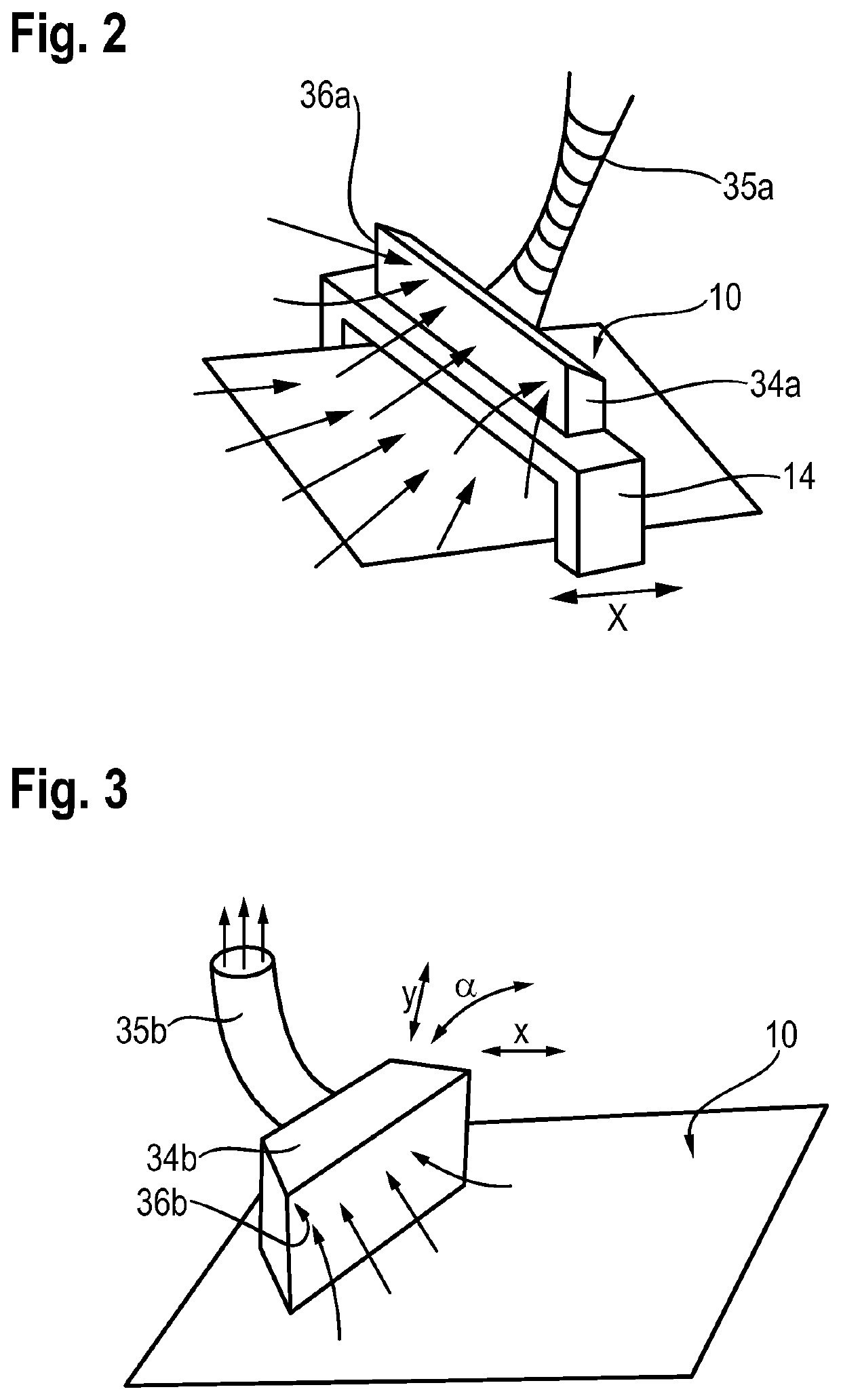
[0041]FIG. 2 schematically shows the movable arrangement of a gas suction nozzle 34a. In this embodiment a gas suction nozzle 34a is attached to the coating device 14, i.e. mechanically connected to the coating device 14, and can be moved together with the coating device 14 over the working plane 10 and the powder layer applied thereon. The movement takes place in a first direction (x direction) to and fro parallel to the working plane. In the first direction the gas suction nozzle 34a has a gas suction opening 36a. In a second direction (y direction) perpendicular to the first direction, but also parallel to the working plane 10, the gas suction nozzle 34a has a width extending approximately over the entire width of the coating device and thus approximately over the entire building area, i.e. the area of the working plane 10 lying within the upper opening of the container 5. The gas suction opening 36a extends approximately over the entire width of the gas suction nozzle 34a.

[0042...

second embodiment

[0049]FIG. 3 schematically shows the movable arrangement of a gas suction nozzle 34b. In this embodiment a gas suction nozzle 34b is arranged freely movably in the processing chamber. It can move in the x direction and in the y direction parallel to the working plane and turn about any angle α about an axis—here perpendicular to the working plane 10. Rotation about any angle (not shown) about an axis parallel to the working plane 10, i.e. a rotation in the direction of the working plane 10 or upwards away from the working plane 10, is also possible. It can thus, in any orientation, be brought to any position of the building area. Through this the width of the gas suction nozzle 34b and its gas suction opening 36b no longer has to extend approximately over the entire width of the building area, but can be much smaller.

[0050]Free movement of the gas suction nozzle 34b can be realized, for example, through installation on a swivel arm that has the required degree of freedom of movement...

third embodiment

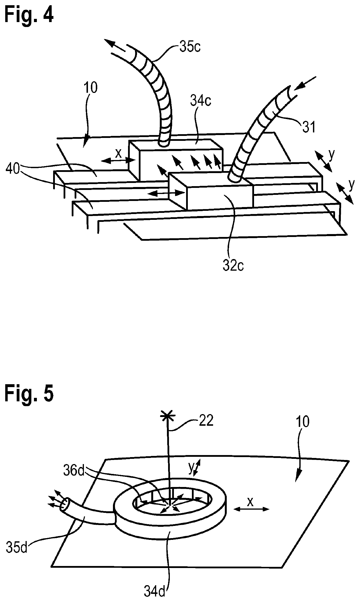
[0051]FIG. 4 schematically shows the movable arrangement of a gas suction nozzle 34c. In this embodiment a gas inlet nozzle 32c and a gas suction nozzle 34c are arranged facing each other on a linear movable portal system 40. The portal system 40 can move the nozzles parallel to each other and with a variable or constant distance from each other in the x direction and y direction parallel to the working plane. This also achieves that the nozzles are brought to every position of the building area, but their orientation and distance from each other and therefore the relative direction and magnitude of the gas flow between them can be maintained. In this embodiment too the nozzles 32c, 34c can have a substantially smaller width than that of the building area 10.


PUM

PropertyMeasurementUnit
distanceaaaaaaaaaa
distanceaaaaaaaaaa
distance d2aaaaaaaaaa

Abstract

A device (1) for producing a three-dimensional object (2) through layer-wise solidifying of build-up material (13) at positions (43) corresponding to a cross-section of the object (2) to be produced in a respective layer comprises a coating device (12-14) for applying a layer of the build-up material (13) on a working plane (10), a solidifying device (20) for the selective solidifying of the build-up material (13) in the applied layer and a gas suction nozzle (34) for extracting gas from the device (1) by suction. The gas suction device (34) is thereby movably arranged and the device (1) is designed to control or to regulate a movement and/or orientation of the gas suction nozzle (34) as a function of a number of reference positions (51, 53, 55a, 55b, 55c, 55d).

Description

TECHNICAL FIELD OF THE INVENTION[0001]The present invention relates to a device for producing a three-dimensional object through layer-wise solidifying of build-up material at the positions corresponding to the cross-section of the object to be produced in the respective layer through the application of energy. It also relates to a control unit for such a device and to a method of moving and / or orientating a gas suction nozzle.BACKGROUND OF THE INVENTION[0002]A device of this type is used, for example, for rapid prototyping, rapid tooling or rapid manufacturing. An example of such a method known by the name “selective laser sintering or laser melting” as well as an associated device for implementing the method are described in document DE 195 14 740 C1. According to this document, by means of a coating device a thin layer of the build-up material in powder form is initially applied and this is then solidified at the positions corresponding to the respective cross-section of the obje...

Claims


Application Information

Patent Timeline
Patent Type & Authority Patents(United States)
IPC IPC(8): B22F3/105B33Y10/00B33Y40/00B29C64/364B33Y30/00B23K26/342B23K26/142B29C64/153B33Y50/02B23K26/70B23K26/16B28B1/00B28B17/00B23K101/00
CPCB22F3/1055B23K26/142B23K26/16B23K26/342B23K26/702B28B1/001B28B17/0081B29C64/153B29C64/364B33Y10/00B33Y30/00B33Y40/00B33Y50/02B22F2003/1056B22F2003/1057B22F2201/10B22F2998/10B22F2999/00B23K2101/001Y02P10/25B22F10/00B22F10/77B22F10/28B22F10/322B22F12/70B29C64/393
Inventor SCHILLING, ALEXANDERFEY, GEORG
Owner EOS ELECTRO OPTICAL SYST
Why Eureka
Try Eureka