Silicon monocrystal production method

a monocrystal and production method technology, applied in the direction of single crystal growth, polycrystalline material growth, chemistry apparatus and processes, etc., can solve the problem of not always preventing, and achieve the effect of reducing the occurrence of dislocation, stable quality and less dislocation

Active Publication Date: 2021-04-20
SUMCO CORP
View PDF22 Cites 0 Cited by
  • Summary
  • Abstract
  • Description
  • Claims
  • Application Information

AI Technical Summary

Benefits of technology

[0014]In the above aspect, no dislocation occurs in the shoulder and the straight body, so that a monocrystalline silicon with a stable quality can be produced.
[0016]Although a typical rotation speed of the crucible for the straight-body-formation step ranges from 2 rpm to 12 rpm, the crucible is rotated at a relatively high speed in the above aspect as described above, thereby reducing the convection of the silicon melt and, consequently, reducing variation in a temperature of the surface of the silicon melt. Such a simple adjustment of the speed of the crucible can reduce remelting due to destabilizing the temperature and, consequently, the generation of the remelt growth area A. Thus, no dislocation occurs in the shoulder and the straight body, so that a monocrystalline silicon with a stable quality can be produced.
[0019]In the above aspect, the rotation speed of the crucible is controlled under the above conditions, reducing not only the dislocation in the straight body but also the uneven distribution of, for instance, oxygen concentration and resistivity.
[0022]In the above aspect, the heating ratio is set larger than 1 (i.e. the volume of heat of the lower heater is set larger than that of the upper heater to enhance the convection that rises from the bottom of the crucible and flows toward the outside of the crucible after reaching the solid-liquid interface. This convection flows in the opposite direction to the direction for convection with an unstable liquid temperature that flows from the surface of the dopant-added melt toward the crystal, thus keeping the melt with an unstable liquid temperature from entering the solid-liquid interface while letting the melt with a relatively stable liquid temperature, which rises from the bottom, flow into the solid-liquid interface. This reduces remelting due to destabilizing the temperature and, consequently, the generation of the remelt growth area A. Thus, no dislocation occurs in the shoulder and the straight body, so that a monocrystalline silicon with a stable quality can be produced.

Problems solved by technology

However, dislocation sometimes occurs at an early stage of crystal growth in the process of producing the monocrystalline silicon to hamper single crystallization, which has proven that the method of Patent Literature 1 cannot always prevent the problem.

Method used


Image

  • Silicon monocrystal production method
  • Silicon monocrystal production method
  • Silicon monocrystal production method

Examples


experiment 1

Between Rotation Speed of Crucible and Dislocation Production Method of Monocrystalline Silicon

examples 1 and 2

[0079]Monocrystalline silicons were produced in Examples 1 and 2 under the same conditions as in Comparative Example 1 except that the crucible was rotated respectively at 16 rpm and 20 rpm during the period when the crucible was rotated at 14 rpm in Comparative Example 1. Table 1 shows the try frequency, dislocation frequency, and dislocation rate.

experiment 2

Between Dislocation and Height of Remelt Growth Area

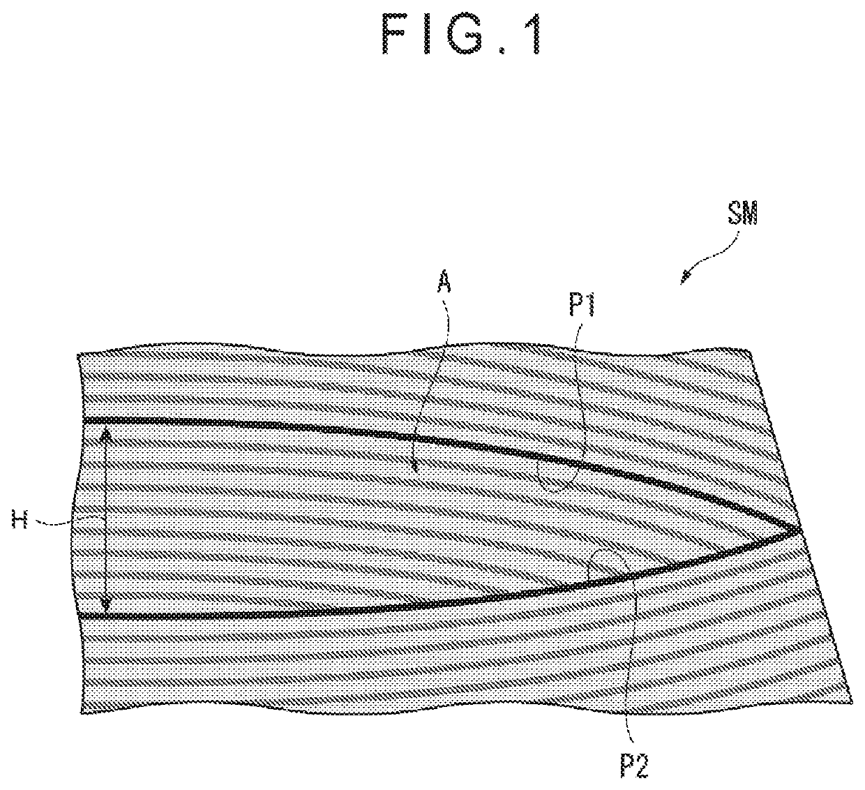
[0087]The monocrystalline silicon of Comparative Example 1, in which dislocation occurred, was vertically cut at a center in a radial direction and the obtained cross section of the shoulder was observed on X-rays to evaluate the number and the height of the remelt growth area(s). The same evaluation was also performed on the monocrystalline silicons of Examples 1, 2 and 5, in which no dislocation occurred. The results are shown in FIG. 6.

[0088]As shown in FIG. 6, the shoulder of each of Examples 1, 2 and 5 had remelt growth areas of less than 200 μm in height but no remelt growth area of 200 μm or more. In contrast, the shoulder of Comparative Example 1 had not only remelt growth areas of less than 200 μm but also ones of 200 μm or more. Further, since no dislocation occurred in the monocrystalline silicons of Examples 3, 4 and 6, the shoulders of Examples 3, 4 and 6 are supposed to have no remelt growth area of 200 μm or more in ...


PUM

PropertyMeasurementUnit
heightaaaaaaaaaa
diameteraaaaaaaaaa
diameteraaaaaaaaaa

Abstract

A production method of a monocrystalline silicon includes: forming a shoulder of the monocrystalline silicon; and forming a straight body of the monocrystalline silicon. In forming the shoulder, the shoulder is formed such that a part of growth striations, which extend radially across the shoulder, has an outer end interrupted by another part of the growth striations not to reach a peripheral portion of the shoulder and that no remelt growth area with a height of 200 μm or more in a growth direction is generated.

Description

TECHNICAL FIELD[0001]The present invention relates to a production method of a monocrystalline silicon.BACKGROUND ART[0002]Low-resistive monocrystalline silicons have recently been demanded. In a known production method of such monocrystalline silicons where an n-type dopant is densely added, single crystallization is sometimes hampered and thus studies have been conducted on prevention of such a problem (see, for instance, Patent Literature 1).[0003]Patent Literature 1 discloses that addition of a large amount of the dopant significantly increases a freezing-point depression to cause compositional supercooling and an abnormal growth (Cell growth), which is different from a silicon growth on a silicon growth face, is induced on a crystal growth interface when such compositional supercooling is large, hampering single crystallization.[0004]According to the production method of Patent Literature 1, which takes into account that a temperature gradient in a silicon melt cannot be direct...

Claims


Application Information

Patent Timeline
Patent Type & Authority Patents(United States)
IPC IPC(8): C30B15/02C30B29/06C30B15/22C30B15/04
CPCC30B29/06C30B15/04C30B15/22C30B15/14C30B15/203C30B15/20
Inventor NARUSHIMA, YASUHITOKUBOTA, TOSHIMICHI
Owner SUMCO CORP
Why Eureka
Try Eureka