Hysteresis comparator
- Summary
- Abstract
- Description
- Claims
- Application Information
AI Technical Summary
Benefits of technology
Problems solved by technology
Method used
Image

Examples
Embodiment Construction
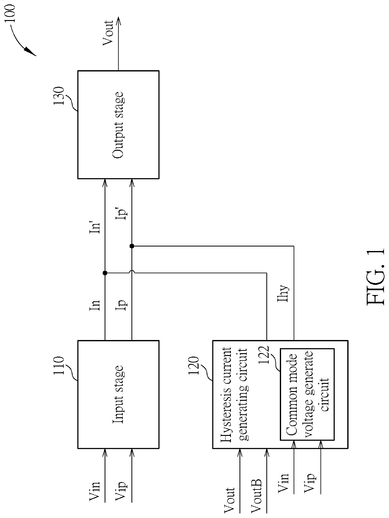
[0010]FIG. 1 is a diagram illustrating a hysteresis comparator 100 according to an embodiment of the present invention. As shown in FIG. 1, the hysteresis comparator 100 comprises an input stage 110, a hysteresis current generating circuit 120 and an output stage 130, wherein the hysteresis current generating circuit 120 comprises a common mode voltage generate circuit 122.
[0011]In the operation of the hysteresis comparator 100, the input stage 110 receives a pair of differential input signals Vin and Vip to generate at least one pair of differential current signals In and Ip. Next, the hysteresis current generating circuit 120 generates at least one hysteresis current Ihy according to an output signal Vout of the hysteresis comparator 100 and the inverse signal VoutB of the output signal Vout, in order to adjust differential current signals In and Ip to generate adjusted differential current signals In′ and Ip′, wherein the common mode voltage detecting circuit 122 in the hysteresi...
PUM
 Abstract
Description
Claims
Application Information
 - Generate Ideas
- Intellectual Property
- Life Sciences
- Materials
- Tech Scout
- Unparalleled Data Quality
- Higher Quality Content
- 60% Fewer Hallucinations
Browse by: Latest US Patents, China's latest patents, Technical Efficacy Thesaurus, Application Domain, Technology Topic, Popular Technical Reports.
© 2025 PatSnap. All rights reserved.Legal|Privacy policy|Modern Slavery Act Transparency Statement|Sitemap|About US| Contact US: help@patsnap.com