Supercharge Your Innovation With Domain-Expert AI Agents!

Circuit carrier and manufacturing method thereof

a technology of circuit carrier and manufacturing method, which is applied in the direction of semiconductor/solid-state device details, electrical apparatus, semiconductor devices, etc., can solve the problems of inability to accurately form vias or circuits in subsequent processes, easy chip shift, and critical impact on the accuracy of subsequent packaging processes

Active Publication Date: 2021-05-04
UNIMICRON TECH CORP
View PDF7 Cites 0 Cited by
  • Summary
  • Abstract
  • Description
  • Claims
  • Application Information

AI Technical Summary

Benefits of technology

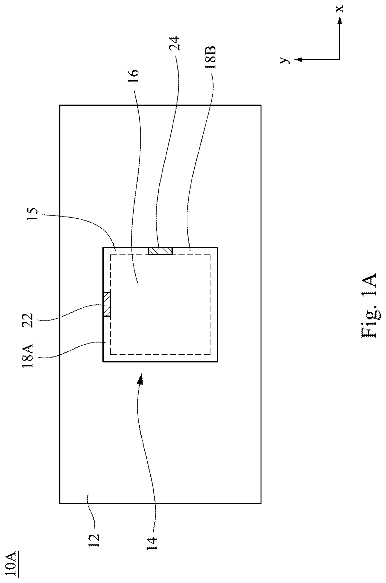
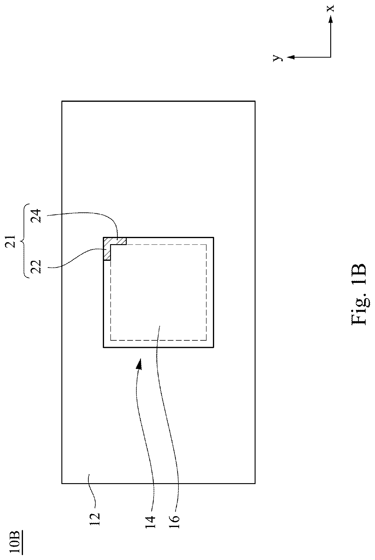
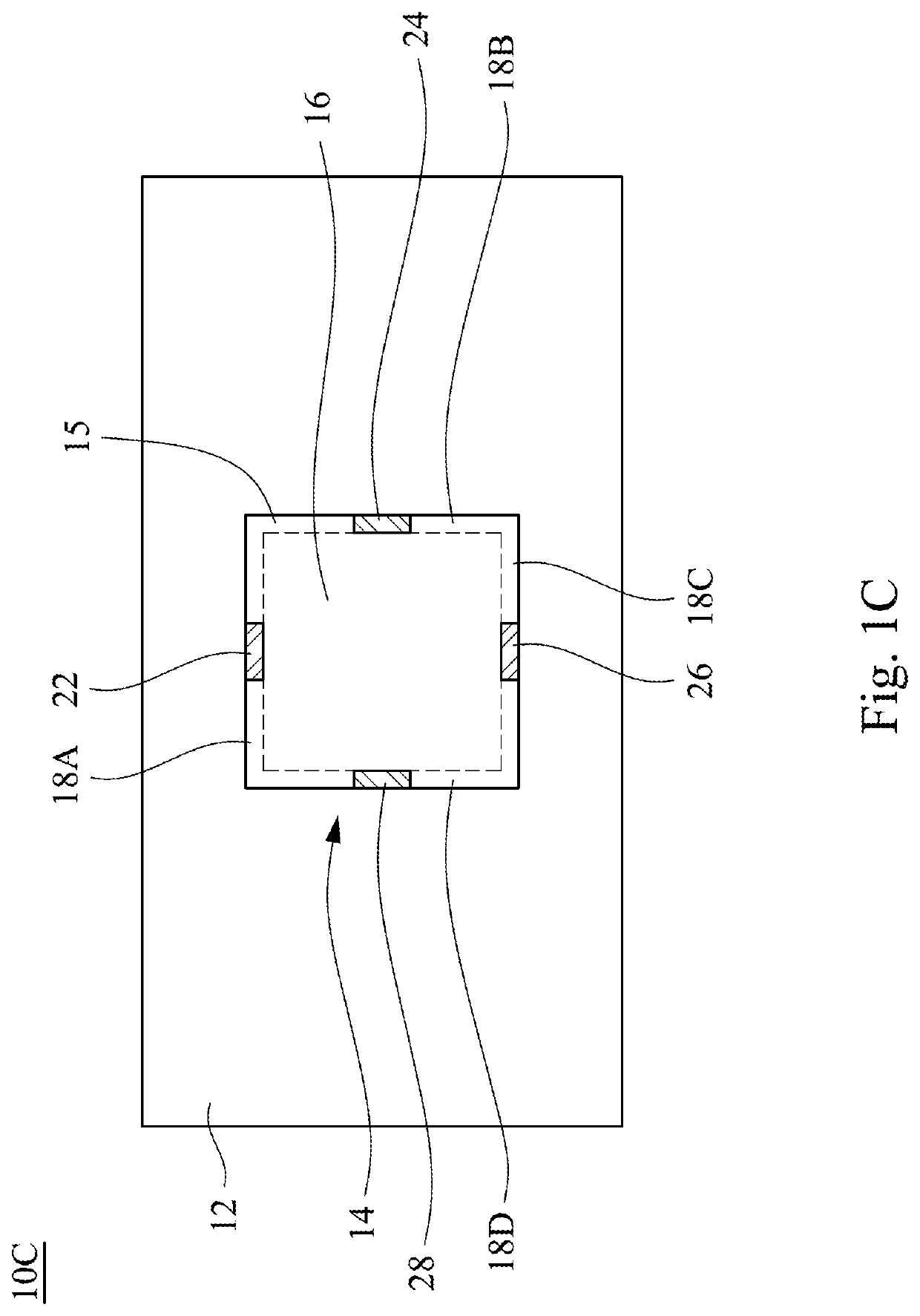
This patent provides a circuit carrier and a method for manufacturing it. The circuit carrier has a metal heat slug with a plurality of circuits, and the first and second fixing pieces are located on the upper surface of the metal heat slug. The first and second fixing pieces can position an electronic component on the metal heat slug. The method involves forming a precursor laminar circuit structure on a substrate, disposing the metal heat slug on the precursor laminar circuit structure, and adding a second dielectric layer to surround the metal heat slug. The positioning of the fixing pieces is achieved through a lithography process. The technical effects of this patent include improved heat transfer, reduced circuit size, and simplified manufacturing process.

Problems solved by technology

Because the circuit carrier has no fixing structure for fixing the chip, the shift of the chip easily occurs during the placement of the chip.
Such shift may easily cause critical impact on the accuracy of the subsequent packaging processes.
The shift of the chip may cause the vias or circuits cannot be formed accurately in the subsequent processes.
Therefore, how to reduce the shift of the chip in the circuit carrier is a critical issue that needs to be solved.

Method used


Image

  • Circuit carrier and manufacturing method thereof
  • Circuit carrier and manufacturing method thereof
  • Circuit carrier and manufacturing method thereof

Examples


Embodiment Construction

[0021]The present disclosure provides many different embodiments, or examples, for implementing different features of this disclosure. Specific examples of components and arrangements are described below to simplify the present disclosure. These are, of course, merely examples and are not intended to be limiting. For example, the formation of a first feature over or on a second feature in the description that follows may include embodiments in which the first and second features are formed in direct contact, and may also include embodiments in which additional features may be formed between the first and second features, such that the first and second features may not be in direct contact. In addition, the present disclosure may repeat reference numerals and / or letters in the various examples. This repetition is for the purpose of simplicity and clarity and does not in itself dictate a relationship between the various embodiments and / or configurations discussed.

[0022]Further, spatia...


PUM


Abstract

A circuit carrier includes a substrate, a laminar circuit structure, a metal heat slug, a first fixing piece, and a second fixing piece. The laminar circuit structure is disposed over the substrate and includes a plurality of dielectric layers and circuits in the dielectric layers. The metal heat slug is disposed in the laminar circuit structure. The first fixing piece is disposed on the first side of the upper surface of the metal heat slug. The second fixing piece is disposed on the second side of the upper surface of the metal heat slug, wherein the first side is perpendicular to the second side. A method of manufacturing a circuit carrier is also provided herein.

Description

CROSS-REFERENCE TO RELATED APPLICATION[0001]This application claims priority to Taiwan Application Serial Number 108128625, filed Aug. 12, 2019, which is herein incorporated by reference in its entirety.BACKGROUNDField of Invention[0002]The present disclosure relates to a circuit carrier structure, particularly a circuit carrier structure having positioning function.Description of Related Art[0003]Generally, when a chip is bonded to a circuit carrier, the chip is mostly disposed on the upper surface of the laminar circuit structure of the circuit carrier. Because the circuit carrier has no fixing structure for fixing the chip, the shift of the chip easily occurs during the placement of the chip. Such shift may easily cause critical impact on the accuracy of the subsequent packaging processes.[0004]The shift of the chip may cause the vias or circuits cannot be formed accurately in the subsequent processes. Therefore, how to reduce the shift of the chip in the circuit carrier is a cri...

Claims


Application Information

Patent Timeline
Patent Type & Authority Patents(United States)
IPC IPC(8): H01L23/498H01L23/13H01L23/367H01L21/48
CPCH01L23/49822H01L21/4857H01L23/13H01L23/367H01L21/486H01L23/145H01L23/3121H01L23/3677H01L23/49827H01L2224/48091H01L2224/48227H01L2224/73265H01L2224/92247H01L2924/181H01L2924/00012H01L2924/00014
Inventor WANG, TZU-HSUAN
Owner UNIMICRON TECH CORP
Features
  • R&D
  • Intellectual Property
  • Life Sciences
  • Materials
  • Tech Scout
  • Unparalleled Data Quality
  • Higher Quality Content
  • 60% Fewer Hallucinations
Learn More