Railway or tramway track

a technology for tramways and rails, applied in railway tracks, temporary pavings, railway tracks, etc., can solve the problems of high noise and vibration emissions of solid railways into the surrounding area, hardly used on transverse railway sleepers and gravel ballast, etc., to reduce the rate of flow and outflow

Active Publication Date: 2021-06-01
EISENREICH JAN
View PDF22 Cites 0 Cited by
  • Summary
  • Abstract
  • Description
  • Claims
  • Application Information

AI Technical Summary

Benefits of technology

[0015]The aim of the invention is achieved by a railway or tramway track, whose principle consists in that noise and vibration reduction elements contain at least one non-humic layer, which absorbs water, reduces its rate of flow and outflow, and allows its evaporation. The non-humic layer is a part of inner components inserted between the rails and / or it is a part of outer components arranged along both outer sides of the rails and / or is composed of at least retention plates, which are inserted between the rails and / or are arranged along at least one outer side of the rails.
[0016]The advantage of the proposed solution is the fact that it can be used both on the tracks with a conventional railway superstructure composed of rails, transverse sleepers and gravel ballast, and on railways with a solid railway composed of rails and a concrete slab without gravel ballast. The solution can be preferably used also on railway tracks leading on bridge constructions, where it can at the same time create escape routes for passengers and operating staff in case of accidents or emergencies.
[0018]In a preferred embodiment, the inner components, outer components and retention plates in the track are secured with the aid of clamp resilient stabilizers, which are made of an elastomer and at the same time damp the noise and vibration coming from the space of the coupling chamber of the rail and / or the flange of the rail, whereby optionally a part of the body of the stabilizer is provided with a continuous shape recess and / or a less rigid material with a higher level of flexibility is used. Such an embodiment of the stabilizer ensures different values of stiffness of the systems of modular components for reducing noise and vibration in the track than is the stiffness of the system of the rail track, especially of the system of the tracks with their fastenings. The transverse stiffness of the stabilizers is therefore appropriately adjusted so that it is smaller than that of the track fastenings mounted in the rail fastening systems. Mounting the inner and outer sandwich components, or retention plates, in a track with a solid railway with stabilizers disposed between the individual rail fastening systems allows visual inspection of these systems and does not block possible repair in case the system is damaged or becomes loose, etc. Between the individual inner and outer components, there are joint gaps at given distances, thus ensuring a nonhomogeneous and electrically insulated split system of components joining one another. The individual stabilizers do not contact each other, by which means they form a non-homogeneous and electrically insulated split system of elastomeric components.
[0022]In a preferred embodiment, the noise and vibration reduction elements are separated on the outer side of the rail from the surroundings of the track by dividing prefabricated components, whereby the noise and vibration reduction elements tightly abut the dividing prefabricated components. Also, these dividing prefabricated components may be provided on its inner or outer surface with an elastomeric layer preventing vibration propagation.

Problems solved by technology

However, it is also the construction of rail vehicles as such and the construction of the railway itself that is the source of noise and vibration.
At high speeds of the trains, noise and vibration are caused by the aerodynamic design of railway vehicles, etc.
These railways do not contain gravel ballast, which would otherwise absorb noise and vibration in the railway track.
Therefore, these solid railways have higher emissions of noise and vibration into the surrounding area than gravel ballasted tracks.
However, the disadvantage of this system is the fact that they can be hardly used on a railway with transverse railway sleepers and gravel ballast.
On the other hand, the solution for reducing the propagation of vibration and noise by forming a compact horizontal pad filling the space between the rails and between the tracks with elastomeric and noise-absorbing elements and / or cultivation layers, especially organic layers with grass or other appropriate plants makes it difficult or completely impossible to perform the control system of rail fastening and to carry out the maintenance of the geometry of the gravel-ballasted tracks by means of tamping.
During the maintenance of rail fastenings and the maintenance of the rails by tamping, it is therefore necessary to dismantle completely the structural layers, which results in partial, but in most cases complete, deterioration of these layers and consequently they have to be replaced with new ones.
Tall urban buildings with a prevalence of vertically oriented surfaces lead to an increase in the amount of shortwave radiation and to its reflection into the adjacent space and thereby they have a negative impact on the climate, causing an increase in local temperature, reducing humidity, affecting wind speed and direction, influencing rainfall in a given area, etc.
Moreover, the soil cover consists of organic components, which are gradually consumed by the growing plants and the structure of the soil cover is gradually becoming denser and, as the case may be, it may also become compacted due to the driving rail vehicles, which results not only in decreasing the vegetative abilities of the plants, but also in reducing the ability of such a soil layer to retain water.
Changes in the water absorption capacity of the soil cover of the track and changes in the homogeneity of the structural layers of the track may, during torrential rains or during times of prolonged rainy periods, even lead to soil erosion and to dangerous undermining of the track grid, which negatively affects the quality and safety of the railway track.
Properly maintained natural lawns on the soil cover of railway tracks are always economically challenging, and these costs are covered largely by public budgets.
Related to this is also the issue of requirements for reducing emissions and noise and vibration propagation both into the surrounding open spaces and within the space of a rail vehicle.
Nevertheless, these requirements can be met by the known systems only to a considerably limited extent, or fulfilling them involves considerable additional costs so as to maintain all the functions of the systems, especially the functions of the green track.

Method used


Image

  • Railway or tramway track
  • Railway or tramway track
  • Railway or tramway track

Examples


Embodiment Construction

[0034]Reference will now be made to embodiments of the invention, one or more examples of which are shown in the drawings. Each embodiment is provided by way of explanation of the invention, and not as a limitation of the invention. For example features illustrated or described as part of one embodiment can be combined with another embodiment to yield still another embodiment. It is intended that the present invention include these and other modifications and variations to the embodiments described herein.

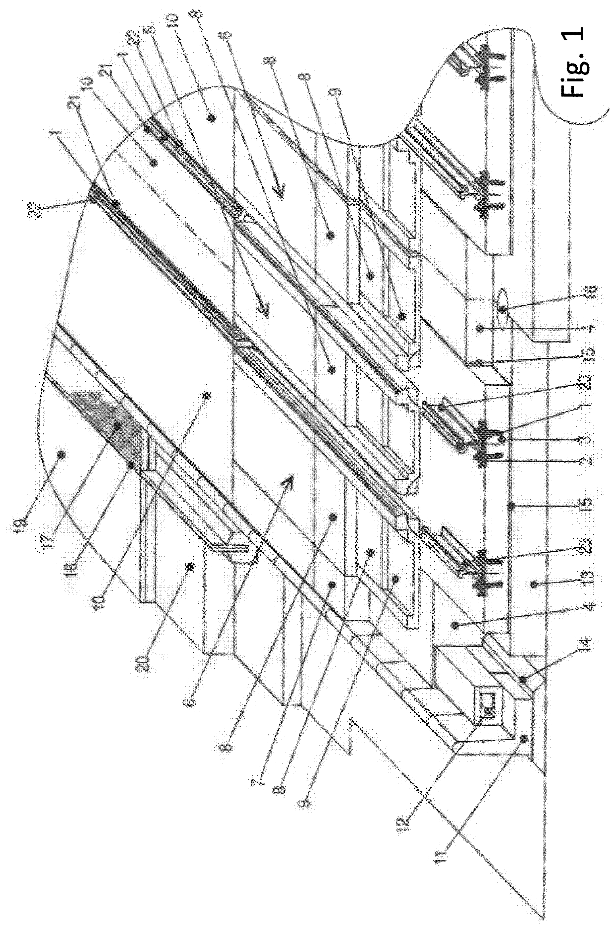
[0035]Several embodiments will be used to explain the invention, illustrated in FIGS. 1 to 5, whereby the principle of the invention is based on the fact that at least one non-humic layer is inserted in the track, whereby this layer absorbs water, reduces its rate of flow and outflow, and at the same time allows its evaporation. By the non-humic humic layer, we understand a layer which does not contain soil, or, more specifically, soil for growing plants.

[0036]FIG. 1 shows an exemp...


PUM


Abstract

A railway or tramway track includes track rails arranged on a foundation surface. Noise and vibration reduction elements are arranged between the track rails and outward of the track rails. The noise and vibration reduction elements include at least one non-humic layer that absorbs water, reduces rate of flow and outflow of the water, and allows evaporation of the water.

Description

TECHNICAL FIELD OF THE INVENTION[0001]The invention relates to a railway or tramway track with noise and vibration reduction elements arranged both inside and outside the track.BACKGROUND[0002]A wide variety of systems are known to reduce noise emissions and vibration from rail vehicles produced due to the contact between the wheel and the rail. These systems are most often based on the structural configuration of a rail fastening system and on a high quality, i.e. smooth finish, of the contact surfaces of the wheel and the rail. However, it is also the construction of rail vehicles as such and the construction of the railway itself that is the source of noise and vibration. At high speeds of the trains, noise and vibration are caused by the aerodynamic design of railway vehicles, etc.[0003]During the construction of railways, it is essential to increase the overall stability of the railway operated in time, to ensure minimum variations in the precise design of the track geometry, t...

Claims


Application Information

Patent Timeline
Patent Type & Authority Patents(United States)
IPC IPC(8): E01B19/00E01C9/06
CPCE01B19/003E01C9/06
Inventor EISENREICH, JAN
Owner EISENREICH JAN
Why Eureka
Try Eureka