Optical coherence tomography system

a coherence tomography and optical coherence technology, applied in the field of 3dimensional imaging technologies, can solve the problems of inability to widely adopt ss-oct by ophthalmologists, limited ss-oct and ss-oct imaging depths, and adverse side effects of coherence revival, so as to suppress coherence revival artifacts, increase the order of coherence revival, and sufficient spectral width

Active Publication Date: 2021-06-01
SVISION IMAGING LTD
View PDF4 Cites 0 Cited by
  • Summary
  • Abstract
  • Description
  • Claims
  • Application Information

AI Technical Summary

Benefits of technology

[0029]Preferably, in the delay line, a single-collimator and a third fiber coupler are shared by the reference arm front section and the reference arm rear section; the reference arm front section is connected to the first port of the third fiber coupler; the second port of the third fiber coupler is connected to the single-collimator; the reference light enters the single-collimator, reaches a reflective optical component, is reflected back along the same path, and passes to the third port of the third fiber coupler; the third port of the third fiber coupler is connected to the second port of the second fiber coupler; and the optical path length of the reference arm front section is greater than the optical path length of the sample arm, with a difference between the two greater than 8 times the cavity length of the swept-source laser. In this implementation, the delay line is simplified, and the single-collimator delay line is more stable and easier to assemble. Moreover, the third fiber coupler has an extra fourth port, which can be used for other purposes, such as laser power monitoring.
[0032]Advantages: the OCT system based on the invention increases the order of the coherence revival artifacts by increasing or decreasing the optical path length of the parasitic or stray reflected light of the delay line components, thereby achieving the effect of suppressing the coherence revival artifacts. Compared with the prior art, the OCT system can achieve sufficient spectral width, is simple and relatively inexpensive, does not cause additional optical losses or polarization mode dispersion (PMD), and can ensure the sensitivity of the system.

Problems solved by technology

However, due to its high price and complexity, SS-OCT has not yet been widely adopted by ophthalmologists.
The imaging depths of SD-OCT and SS-OCT are limited by different physical limitations.
However, coherence revival has an adverse side effect.
Unlike SD-OCT, the coherence revival effect in SS-OCT leads to artifacts in the OCT image.
For SS-OCT, however, light signals with the optical path length difference greater than the imaging depth could still cause relatively strong interference via the coherence revival effect.
As a result, SS-OCT is much more vulnerable towards the artifacts caused by reflection or scattering of components in an optical path.
This is one of the technological challenges that have hindered the further development of SS-OCT.
However, this method has limitations when the cavity length of the swept-source laser is relatively short.
Therefore, this method can only be used when the cavity length of the swept-source laser is much greater than the required imaging depth.
However, the optical isolator cannot easily achieve a sufficient spectral bandwidth, is relatively expensive, and could cause additional light losses and polarization mode dispersion (PMD), thereby reducing the system sensitivity.
However, these laser sources have not yet reached technological maturity for commercial SS-OCT systems.
In practical optical system design, due to some specific constraints, the above-mentioned mitigation methods may not be applicable.
For example, for the coherence revival artifacts caused by stray light of the optical delay line in the reference arm (see below for details), the above-mentioned methods are not effective.
These optical components are likely to cause parasitic reflections.
Because there are many components in the delay line that can produce parasitic reflections and the optical path length of the delay line itself can be adjusted within a certain range, this makes it difficult for the optical system design to ensure that the differences between the optical path lengths of all these components (not only limited to E and G in FIG. 4) and the optical path length of the measured sample (D in FIG. 4) can completely avoid the integer multiples of the cavity length of the swept-source laser (A in FIG. 4).
Based on such a system design, the coherence revival artifacts due to the parasitic reflections of the delay line components are likely to be present, which affects the structure image of the true sample.
Other components in the delay line, such as the fiber tips E and G, are also prone to produce the coherence revival artifacts.

Method used


Image

  • Optical coherence tomography system
  • Optical coherence tomography system
  • Optical coherence tomography system

Examples


embodiment i

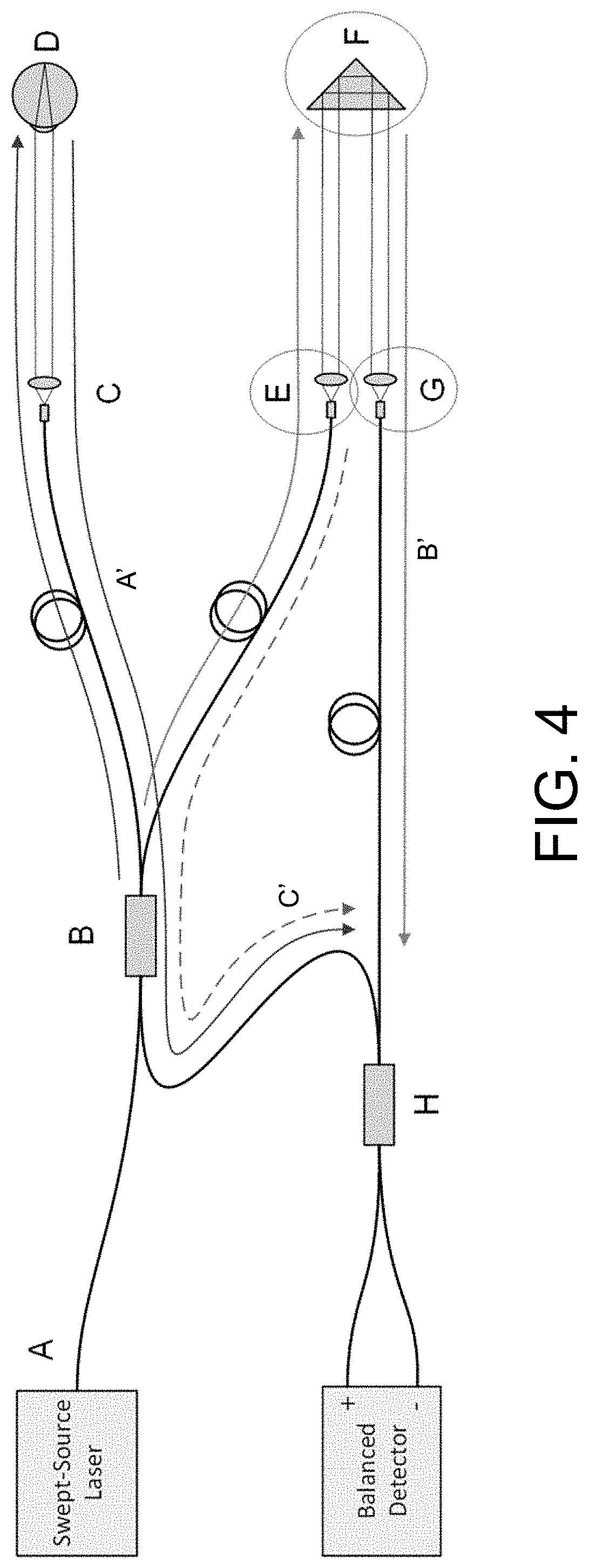
[0045]An optical coherence tomography (OCT) system includes a swept-source laser 1, a Mach-Zehnder interferometer, and a balanced detector 2. The interferometer includes a first fiber coupler 3, a second fiber coupler 4, a sample arm 5 and a reference arm. The reference arm includes a reference arm front section 61, a reference arm rear section 62 and a delay line 63. Each of the first fiber coupler 3 and the second fiber coupler 4 includes a first port, a second port, a third port and a fourth port; the output of the swept-source laser 1 is connected to the first port of the first fiber coupler 3. The second port of the first fiber coupler 3 is connected to the sample arm 5. The third port of the first fiber coupler 3 is connected to the reference arm front section 61. The fourth port of the first fiber coupler 3 is connected to the first port of the second fiber coupler 4. The tail end of the reference arm front section 61 is connected to the reference arm rear section 62 through ...

embodiment ii

[0049]Embodiment II is different from Embodiment I in that Embodiment II achieves the same effect of suppressing the coherence revival artifacts by increasing the fiber length of the reference arm rear section 62 and decreasing the fiber length of the reference arm front section 61. Other parts of the system are the same as those in Embodiment I.

[0050]Let us assume that the sum of the optical path length of the reference arm front section 61 and the round-trip optical path length of the delay line 63 be L, then L should be less than the optical path length of the sample arm, with a difference greater than 8 times the cavity length of the swept-source laser. That is, the following condition needs to be met:[0051]OPL(B→E→F→G)

embodiment iii

[0052]The delay line 63 in Embodiment III is different from that in Embodiment I and Embodiment II. In the delay line 63, a single-collimator 631 (which serves as both the transmitting collimator and the receiving collimator) and a third fiber coupler 7 are shared by the reference arm front section and the reference arm rear section. The third fiber coupler 7 includes a first port, a second port and a third port. The reference arm front section 61 is connected to the first port of the third fiber coupler 7. The second port of the third fiber coupler 7 is connected to the single-collimator. The reference light enters the single-collimator, reaches the reflective optical component 632 (a corner reflector in the present embodiment), is reflected back along the same path, and passes to the third port of the third fiber coupler 7. The third port of the third fiber coupler 7 is connected to the second port of the second fiber coupler 4. Other parts are the same as those in Embodiment I an...


PUM


Abstract

An optical coherence tomography system, includes a swept-source laser, a Mach-Zehnder interferometer and a balanced detector. The interferometer includes a first fiber coupler, a second fiber coupler, a sample arm and a reference arm. The reference arm includes a reference arm front section, a reference arm rear section and a delay line. A tail end of the reference arm front section is connected to the reference arm rear section through the delay line. The first fiber coupler is configured to split the output light of the swept-source into a sample light and a reference light and distribute the returned sample light to the second fiber coupler. A difference between the optical path length of a parasitic reflected signal of the delay line reaching the second fiber coupler and the optical path length of the sample light is greater than 8 times the cavity length of the swept-source laser.

Description

CROSS-REFERENCE TO RELATED APPLICATION[0001]This application is a continuation of international PCT application serial no. PCT / CN2018 / 103869, filed on Sep. 4, 2018, which claims the priority benefit of Chinese application no. 201710904860.1, filed on Sep. 29, 2017. The entirety of each of the above-mentioned patent applications is hereby incorporated by reference herein and made a part of this specification.TECHNICAL FIELD[0002]The invention relates to 3-dimensional imaging technologies, and more particularly relates to a swept-source optical coherence tomography (OCT) system.BACKGROUND INFORMATION AND PRIOR ART[0003]Optical coherence tomography (OCT) is a 3-dimensional imaging technology that has wide range of applications, especially for biomedical imaging. The OCT technology has many advantages such as high resolution, high imaging speed, and high sensitivity. Since commercial OCT imaging systems first came to market in 1996, the OCT technology has greatly promoted the developmen...

Claims


Application Information

Patent Timeline
Patent Type & Authority Patents(United States)
IPC IPC(8): G01B9/02A61B3/10
CPCG01B9/02091G01B9/02004G01B9/02027G01B9/02059A61B3/102A61B3/0016A61B5/0066A61B5/7203
Inventor WEI, XINGHUANG, BINGJIECHEN, JUNPENG, XIANZHAO
Owner SVISION IMAGING LTD
Why Eureka
Try Eureka