Method for checking the design of locking assemblies

a technology of locking assembly and design, applied in the field of mechanical transmission, can solve the problems of time-consuming and material-wasting, and achieve the effects of simple operation, high applicability, and high safety coefficient of bolts

Active Publication Date: 2021-06-29
TAIYUAN UNIVERSITY OF SCIENCE AND TECHNOLOGY
View PDF16 Cites 0 Cited by
  • Summary
  • Abstract
  • Description
  • Claims
  • Application Information

AI Technical Summary

Benefits of technology

[0004]An objective of the present invention is to provide a novel check method that has advantages of simple operation and high applicability, provides stable and reliable result, can improvethe design and manufacture efficiency, in order to solve the technical problems that the existing methods for checking the design of locking assemblies are time-consuming, material-wasting and lack of comprehensive check factors.
[0037]In the present invention, a torque that can be transferred after the locking assemblies are locked is calculated according to the number of selected bolts and a pre-tightening moment of the bolts, and the calculated torque is compared with the designed maximum torque to calculate a torque safety coefficient; then, a resultant stress of components is calculated, and the resultant stress is compared with a yield strength of the material of the components to calculate a strength safety coefficient; and finally, a pre-tightening force is obtained according to a given pre-tightening moment of the bolts, a maximum equivalent stress is calculated, and a safety coefficient of the bolts is obtained. By this method, it can be verified whether a maximum torque can be transferred after the locking assemblies is locked, whether a maximum bending moment is borne, and whether the material of components undergoes plastic failure. This method in the present invention has advantages of simple operation and high applicability, and can effectively verify the rationality of design of locking assemblies, reduce the manufacture risk and increase the yield of products. Compared with the prior art, the present invention provides for stable and reliable check result and improves the design and manufacture efficiency.

Problems solved by technology

Traditionally, the check is carried out only by finite element simulation and experimental testing, both of which are time-consuming and material-wasting.

Method used


Image

  • Method for checking the design of locking assemblies

Examples


Embodiment Construction

[0052]The present invention will be further described below with reference to the accompanying drawings and by embodiments.

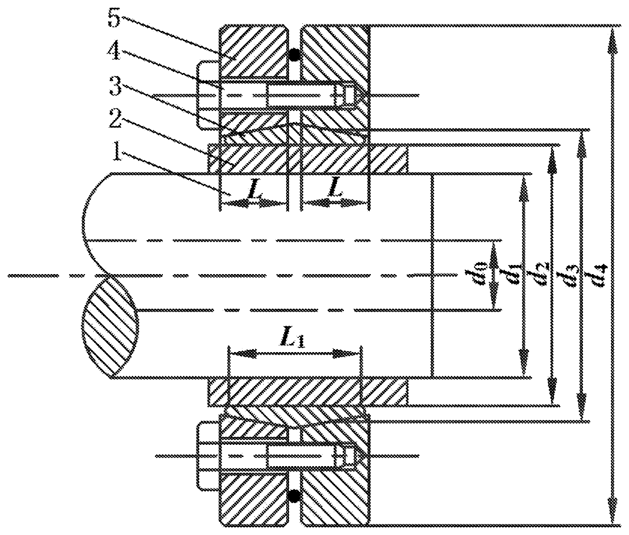
[0053]As shown in FIG. 1, the locking assemblies consist of an inner ring, an outer ring and bolts. The locking assembliesaresheathed on the bushing and the spindle. The check method comprises steps of:

[0054]1) calculating an axial force generated by bolts:

[0055]calculating, according to the number n of selected bolts and a pre-tightening moment M0, an axial force generated by bolts:

[0056]Fa=M0⁢nkd(1)

[0057]where, Fa is an axial force generated by the bolts, d is a diameter of the bolts, M0 is a pre-tightening moment of the bolts, and k is a moment coefficient, the value of which is 0.11 to 0.15;

[0058]determining, according to a size of the locking assemblies and by force analysis, a contact pressure p3 between the inner ring and the outer ring:

[0059]p3=Fa⁡(1-μ1⁢⁢tan⁢⁢β)L⁢⁢π⁢⁢d3⁡(tan⁢⁢β+μ1)(2)

[0060]where, L is a length of the outer ring, d3 is a mean diameter of ...


PUM

PropertyMeasurementUnit
outer diameteraaaaaaaaaa

Abstract

A method for checking the design of locking assemblies is provided. A pressure on each contact surface and a torque that can be transferred by a spindle and a bushing after locking assemblies are locked are calculated. The calculated torque is compared with the designed maximum transferable torque to calculate a torque safety coefficient. Based on a minimum fit clearance, a resultant stress of components is calculated and is compared with a yield strength of the material of the components to calculate a strength safety coefficient of the components. A pre-tightening force of the bolts is obtained according to a given pre-tightening moment of the bolts. A maximum equivalent stress of the bolts is calculated to obtain a safety coefficient of the bolts. This method is able to be applied to the manufacturing of the locking assemblies.

Description

CROSS-REFERENCE TO RELATED APPLICATIONS[0001]This application claims the benefit of priority from Chinese Patent Application No. CN201910098828.8, filed on Jan. 31, 2019. The content of the aforementioned application, including any intervening amendments thereto, is incorporated herein by reference in its entirety.TECHNICAL FIELD[0002]The present invention relates to a method for checking the design of locking assemblies, belonging to the technical field of mechanical transmission.BACKGROUND OF THE PRESENT INVENTION[0003]As a basic connector for connecting drive parts in a mechanical drive system, locking assemblies function to bear loads, transfer torque and provide overload protection for other drive parts. According to their shape, the locking assemblies include single-cone locking assemblies and double-cone locking assemblies. Traditionally, the check is carried out only by finite element simulation and experimental testing, both of which are time-consuming and material-wasting....

Claims


Application Information

Patent Timeline
Patent Type & Authority Patents(United States)
IPC IPC(8): G01L5/00F16D1/09
CPCG01L5/0042F16D1/09G01L5/0004G01L5/24F16D1/095
Inventor WANG, JIANMEINING, KEHOU, DINGBANG
Owner TAIYUAN UNIVERSITY OF SCIENCE AND TECHNOLOGY
Why Eureka
Try Eureka