Method for selection of Raman excitation wavelengths in multi-source Raman probe

a raman probe and wavelength selection technology, applied in the field of spectroscopy, can solve the problems of reducing the sensitivity of the silicon ccd detector that captures spectrometer signals, the inability to extract the latency, and the failure of references to disclose the means for selecting wavelengths used in spectral analysis, so as to enhance the performance of quantitative analysis and enhance the quantitative analysis of target materials. , the effect of enhancing the signal to noise ratio

Active Publication Date: 2021-07-20
INNOVATIVE PHOTONICS SOLUTIONS INC
View PDF4 Cites 5 Cited by
  • Summary
  • Abstract
  • Description
  • Claims
  • Application Information

AI Technical Summary

Benefits of technology

[0020]The Raman spectral concatenation concept described herein allows use of a single, relatively compact spectrometer to collect both Fingerprint and Stretch Raman spectra and a method for selecting the laser source wavelengths to provide for enhanced quantitative analysis of target material under investigation. In accordance with the principles of the invention, the Fingerprint spectrum is captured using one excitation wavelength, whereas the Stretch spectrum is captured using a second wavelength selected based on a quantum efficiency of the spectrometer and the first wavelength. The selection of one or more of the laser source wavelengths in the manner disclosed, herein, provides for enhanced signal to noise ratio so as to enhance the performance of a quantitative analysis of a target material under investigation.

Problems solved by technology

Many Raman measurements suffer from fluorescence, which forces usage of longer wavelength (lower energy) excitation lasers to mitigate against the fluorescent signal overwhelming the Raman signal, thereby making the latter impossible to extract.
Usage of longer excitation wavelengths facilitates extraction of Raman signals from fluorescent samples but at a cost of reduced sensitivity in the silicon CCD detectors that capture spectrometer signals.
However, the references fail to disclose the means for selecting wavelengths used in the spectral analysis based on the material selected and the characteristics of the spectrometer utilized.

Method used


Image

  • Method for selection of Raman excitation wavelengths in multi-source Raman probe
  • Method for selection of Raman excitation wavelengths in multi-source Raman probe
  • Method for selection of Raman excitation wavelengths in multi-source Raman probe

Examples


Embodiment Construction

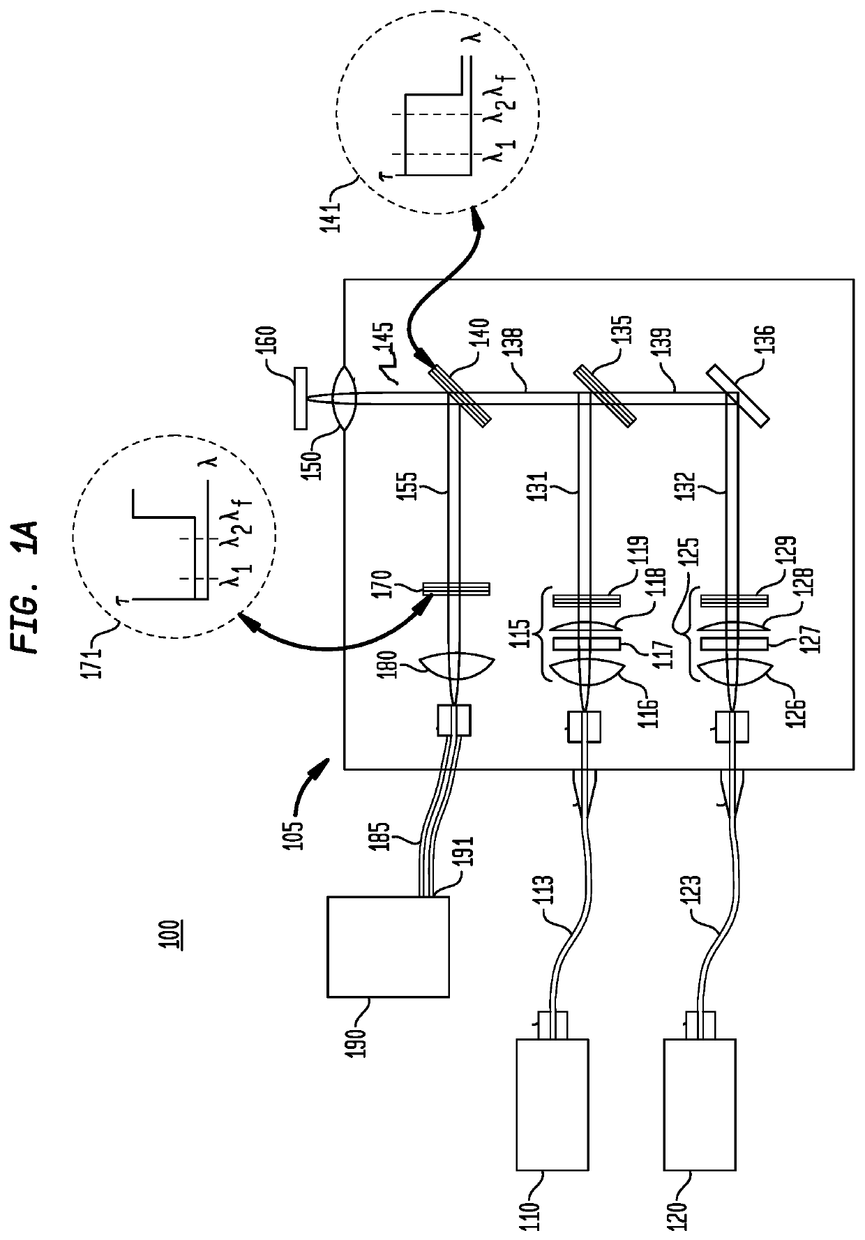
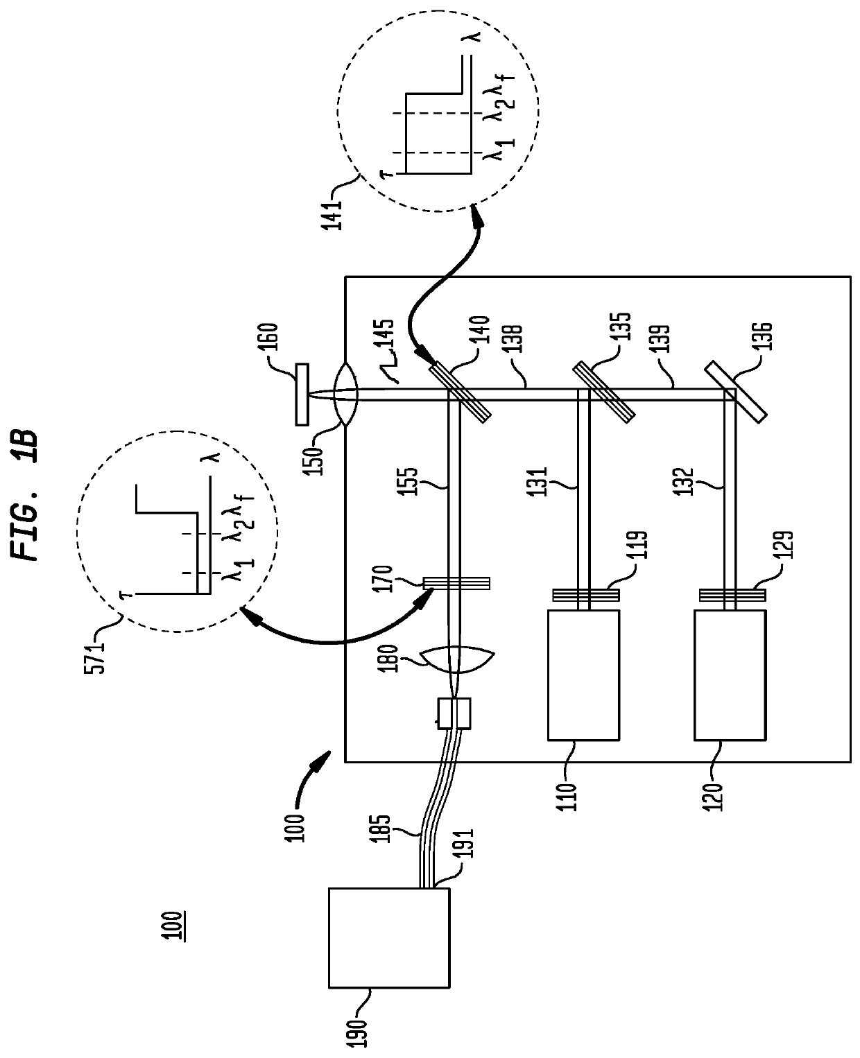
[0046]FIG. 1A illustrates a block diagram of an exemplary embodiment of a compact dual-wavelength Raman probe as is disclosed, for example, U.S. Pat. No. 10,359,313, which discloses the use of diode lasers as the light sources in Raman spectroscopy.

[0047]In this exemplary embodiment, a dual wavelength Raman probe 100 includes a housing 105 and two external laser sources 110 and 120, coupled via optical fibers 113 and 123, respectively, to the internal optics within housing 100. The lasers 110 and 120 may emit light in a single spatial mode or in multiple spatial modes.

The laser sources 110 and 120 may be any laser device or system; preferably laser sources 110 and 120 are wavelength-stabilized laser sources having narrow bandwidth.

[0048]One class of lasers that may be used as a wavelength-stabilized laser source is an external cavity laser. See, for example, U.S. Pat. Nos. 9,059,555 and 9,577,409, which are assigned to the assignee of the instant application and whose contents are i...


PUM


Abstract

A method is disclosed for providing enhanced quantitative analysis of materials by a dual-laser Raman probe wherein the wavelengths of the lasers used to illuminate a target object are selected in a manner to improve and enhance the quantitative analysis performance of the Raman signals.

Description

RELATED PATENTS[0001]This Invention disclosed, herein, is related to that subject matter recited and taught in U.S. Pat. No. 10,359,313, the contents of which are incorporated by reference, herein.FIELD OF THE INVENTION[0002]This invention relates to the field of spectroscopy and more particularly to a compact Raman spectroscopy system and method for providing enhanced quantitative analysis for process controlBACKGROUND OF THE INVENTION[0003]Raman spectroscopy is a well-known technique that can be used to observe vibrational, rotational and other low-frequency modes in molecules. Raman scattering is an inelastic process whereby monochromatic light typically provided by a laser interacts with molecular vibrations phonons or other excitations resulting in the energy of the laser photons being shifted up or down. Due to conservation of energy the emitted photon gains or loses energy equal to energy of the vibrational state.[0004]Many Raman measurements suffer from fluorescence, which f...

Claims


Application Information

Patent Timeline
Patent Type & Authority Patents(United States)
IPC IPC(8): G01J3/44G01N21/65
CPCG01N21/65G01N2201/0636G01N2201/06113
Inventor CHARACHE, GREG W.RUDDER, SCOTT L.
Owner INNOVATIVE PHOTONICS SOLUTIONS INC
Why Eureka
Try Eureka