
Pressure back-up valve

a technology of pressure backup valve and valve body, which is applied in the direction of valve housing, servomotor, mechanical equipment, etc., can solve the problems of increasing transmission efficiency, pressure loss, disadvantage, etc., and achieve the effect of power loss and highest possible efficiency

Active Publication Date: 2021-08-31
ZF FRIEDRICHSHAFEN AG
View PDF5 Cites 0 Cited by
  • Summary
  • Abstract
  • Description
  • Claims
  • Application Information

AI Technical Summary

Benefits of technology

This design minimizes the power loss and system pressure generated by the gear pump, enhancing the overall efficiency of the automatic transmission by ensuring the clutch pressure corresponds to the system pressure, thereby reducing energy consumption and improving torque transmission efficiency.

Problems solved by technology

Due to the lowering of the pressure generated by the gear pump, a support torque of the gear pump and, therefore, the power loss of the automatic transmission decrease according to the pressure reduction, which results in an increase of the transmission efficiency.
The pressure loss, which arises during the through-flow of the check valve, is disadvantageous, however.
Since this elevated pressure must be additionally generated by the gear pump, this has a disadvantageous effect on the efficiency of the automatic transmission.

Method used


Image

  • Pressure back-up valve
  • Pressure back-up valve
  • Pressure back-up valve

Examples


Embodiment Construction

[0038]Reference will now be made to embodiments of the invention, one or more examples of which are shown in the drawings. Each embodiment is provided by way of explanation of the invention, and not as a limitation of the invention. For example, features illustrated or described as part of one embodiment can be combined with another embodiment to yield still another embodiment. It is intended that the present invention include these and other modifications and variations to the embodiments described herein.

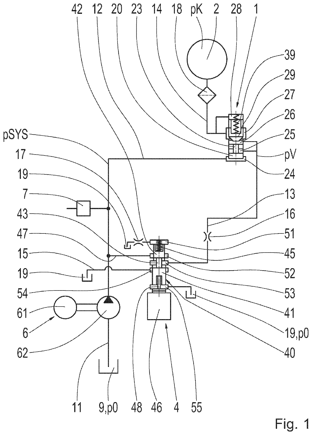
[0039]FIG. 1 shows a diagrammatic part view of a hydraulic circuit diagram of a hydraulic system according to example aspects of the invention for a transmission, in particular for an automatic transmission for an electric drive. The hydraulic system includes a first example embodiment of a pressure back-up valve 1, a shift element 2, a clutch valve 4 as a pressure-adjusting unit, an electrically driven gear pump 6 for generating a hydraulic pressure and flow, as well as a system ...


PUM


Abstract

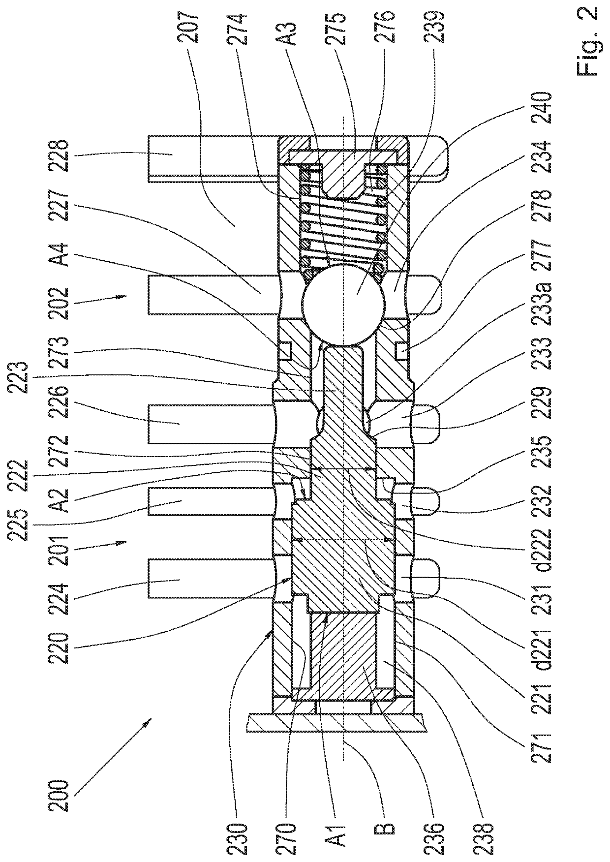
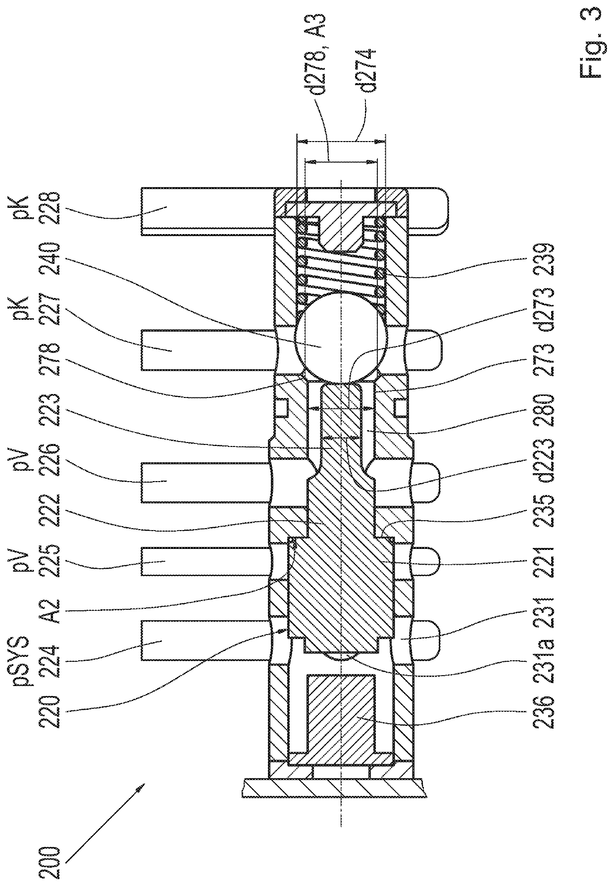
A pressure back-up valve (300) includes a release piston (320) movable between first and second stop positions and a closing body (340) movable to a closing position in which this separates first and second connection pressure chambers (327, 326) when the release piston (320) is in a first stop position. The release piston (320) moves the closing body (340), in the second stop position, into an opening position. The release piston (320) is pressurizable on a first pressure surface (A1) from a first side via a third connection pressure chamber (324) and on a second pressure surface (A2) from a second side via a second connection pressure chamber (326). The closing body (340) is pressurized, in the closing position, from a first side via the second connection pressure chamber (326) on a first pressure surface (A4) and from a second side via the first connection pressure chamber (327) on a second pressure surface (A3) of the closing body (34).

Description

CROSS-REFERENCE TO RELATED APPLICATION[0001]The present application is related and has right of priority to German Patent Application No. 10 2019 208 614.4 filed on Jun. 13, 2019, which is incorporated by reference in its entirety for all purposes.FIELD OF THE INVENTION[0002]The invention relates generally to a pressure back-up valve for a hydraulic system of a transmission, a hydraulic system including the aforementioned pressure back-up valve for a transmission, a transmission for an electric drive including this type of hydraulic system, and a method for operating the hydraulic system.BACKGROUND[0003]DE 10 2014 216 580 A1 of the applicant describes a hydraulic system including a pressure back-up valve for an automatic transmission, in the case of which, after an actuation of the shift element, the pressure that acts upon the shift element in a clutch cylinder with the aid of the pressure back-up valve. Therefore, the shift element remains engaged regardless of a system pressure g...

Claims


Application Information

Patent Timeline
Patent Type & Authority Patents(United States)
IPC IPC(8): F16H51/00F16H61/00F16K11/02F16H61/02F15B11/16
CPCF16H61/0021F15B11/16F16H61/0204F16H61/0251F16K11/02F15B2211/20515F15B2211/20538F15B2211/50F16H2061/0253F16H61/30F16H61/28F15B13/02F16K11/056F16K11/07F16K3/246F16K27/0245F16K27/041F16H2061/0279
Inventor LANGENBACHER, FLORIANSCHMIDT, TOBIASMARTIN, HANS-JOACHIMNOVAK, RAINER
Owner ZF FRIEDRICHSHAFEN AG
Learn More