Eureka AIR delivers breakthrough ideas for toughest innovation challenges, trusted by R&D personnel around the world.

Semiconductor device with self-aligned landing pad and method for fabricating the same

Active Publication Date: 2021-09-14
NAN YA TECH
View PDF1 Cites 3 Cited by
  • Summary
  • Abstract
  • Description
  • Claims
  • Application Information

AI Technical Summary

Benefits of technology

This patent aims to solve the issue of misalignment in the manufacturing process of semiconductor devices. It proposes a method using a self-aligned landing pad with metal silicide and a tapered profile capacitor contact, which reduces misalignment between the capacitor structure and landing pad. Additionally, a coverage layer can prevent the formation of defects and improve the yield of the semiconductor device.

Problems solved by technology

However, a variety of issues arise during the scaling-down process and impact the final electrical characteristics, quality, and yield.
Therefore, challenges remain in achieving improved performance, quality, yield, and reliability.

Method used


Image

  • Semiconductor device with self-aligned landing pad and method for fabricating the same
  • Semiconductor device with self-aligned landing pad and method for fabricating the same
  • Semiconductor device with self-aligned landing pad and method for fabricating the same

Examples


Embodiment Construction

[0050]The following disclosure provides many different embodiments, or examples, for implementing different features of the provided subject matter. Specific examples of components and arrangements are described below to simplify the present disclosure. These are, of course, merely examples and are not intended to be limiting. For example, the formation of a first feature over or on a second feature in the description that follows may include embodiments in which the first and second features are formed in direct contact, and may also include embodiments in which additional features may be formed between the first and second features, such that the first and second features may not be in direct contact. In addition, the present disclosure may repeat reference numerals and / or letters in the various examples. This repetition is for the purpose of simplicity and clarity and does not in itself dictate a relationship between the various embodiments and / or configurations discussed.

[0051]F...


PUM


Abstract

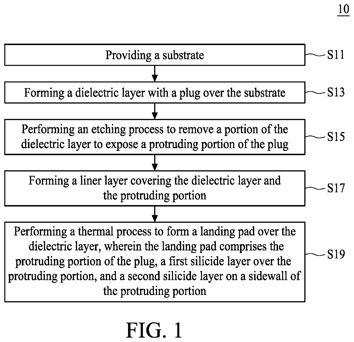
The present application discloses a semiconductor device with a self-aligned landing pad and a method for fabricating the semiconductor device. The semiconductor device includes a substrate, a dielectric layer disposed over the substrate, a plug disposed in the dielectric layer, and a self-aligned landing pad disposed over the dielectric layer. The method includes: providing a substrate; forming a dielectric layer with a plug over the substrate; performing an etching process to remove a portion of the dielectric layer to expose a protruding portion of the plug; forming a liner layer covering the dielectric layer and the protruding portion; and performing a thermal process to form a landing pad over the dielectric layer in a self-aligned manner. The self-aligned landing pad comprises a protruding portion of the plug, a first silicide layer disposed over the protruding portion, and a second silicide layer disposed on a sidewall of the protruding portion.

Description

TECHNICAL FIELD[0001]The present disclosure relates to a semiconductor device and a method for fabricating the semiconductor device, and more particularly, to a semiconductor device with a self-aligned landing pad and a method for fabricating the semiconductor device.DISCUSSION OF THE BACKGROUND[0002]Semiconductor devices are used in a variety of electronic applications, such as personal computers, cell phones, digital cameras, and other electronic equipment. The dimensions of semiconductor devices are continuously being scaled down to meet the increasing demand of computing ability. However, a variety of issues arise during the scaling-down process and impact the final electrical characteristics, quality, and yield. Therefore, challenges remain in achieving improved performance, quality, yield, and reliability.[0003]This Discussion of the Background section is provided for background information only. The statements in this Discussion of the Background are not an admission that the...

Claims


Application Information

Patent Timeline
IPC IPC(8): H01L27/108H01L21/768
CPCH01L27/10855H01L21/7687H01L21/76889H01L21/76897H01L27/10814H01L27/10823H01L21/76885H01L21/76804H01L21/76895H10B12/315H10B12/485H10B12/0335H10B12/482H10B12/34
Inventor CHEN, TE-YIN
Owner NAN YA TECH
Why Eureka
Eureka Blog
Learn More