Rapid consolidation and compaction method for soil improvement of various layers of soils and intermediate geomaterials in a soil deposit

a soil deposit and intermediate geomaterial technology, applied in the direction of bulkheads/piles, construction, foundation engineering, etc., can solve the problem of not being able to pull out the pipe section out of the ground, and achieve the effect of reducing the cost, increasing the density of sandy soil, and reducing the cost of using the rapid consolidation and compaction method

Active Publication Date: 2021-09-21
GUPTA RAMESH CHANDRA
View PDF2 Cites 1 Cited by
  • Summary
  • Abstract
  • Description
  • Claims
  • Application Information

AI Technical Summary

Benefits of technology

[0010]As explained above, the rapid consolidation and compaction method is installed to increase the density of both sandy and clayey materials. Since the sandy material is very economical with much lower cost as compared to jet grouted columns, columns of cement or lime mixed with clayey material or Geopiers, the cost of using the rapid consolidation and compaction method shall be much lower and could save millions of dollars on a big project. The rapid consolidation and compaction method shall densify the (i) very soft to soft cohesive soil to stiff or very stiff cohesive soil, (ii) medium stiff cohesive soil to stiff or very stiff cohesive soil, (iii) stiff cohesive soil to very stiff cohesive soil, and (iv) very stiff cohesive soil to hard or very hard soil cohesive soil, depending on the selected spacing between the adjoining porous displacement piles and relative density of compacted sandy soil in the porous displacement piles. Similarly, the rapid consolidation and compaction method shall compact sandy soil from (i) very loose (relative density less than 15%) to medium dense (relative density between 35 and 65%), (ii) loose (relative density between 15 and 35%) to medium or dense sand (relative density between 65 and 85%), (iii) from medium dense to dense sand, and (iv) from dense to very dense (relative density greater than 85%), depending on the selected spacing between the adjoining porous displacement piles and relative density of compacted sandy soil in the porous displacement piles. When densification to higher densities of in-situ soils is required then the relative density of the sandy material in porous displacement piles more than 70% even up to 100% may be selected for the compacted sandy material in the displacement pipe section with removable end plate, which after installation is pulled out of the ground to form a porous displacement pile. Both the densified in-situ clayey silty soil and in-situ sandy soil in a layer to the selected depth below ground surface shall be capable to provide support to the foundation of a structure with adequate bearing capacity and minimum settlements. During construction of the structure on densified in-situ soil, if any excess pore-water pressure develops, shall quickly dissipate and small settlement shall occur before the structure reaches full height. No embankment as required for the sand drains or PVC drains and waiting for consolidation to occur for 6 months to more than a year shall be needed when the RCCM has been selected. Therefore, progress of construction shall become very fast, which is very important for highway projects for expansion or widening of existing roads and highways or also for support of the foundations of various structures.

Problems solved by technology

In sand drain technology, embankment is placed on the site area to consolidate and densify the area, which also results in densification of sand drains which consists of loosely filled sand, but Mars (1978) method does not use the embankment to be built over the area where the loosely filled pebbles etc. have been filled in the vertical holes.
In many cases, it may not be practical to pull out the pipe section out of the ground.

Method used


Image

  • Rapid consolidation and compaction method for soil improvement of various layers of soils and intermediate geomaterials in a soil deposit
  • Rapid consolidation and compaction method for soil improvement of various layers of soils and intermediate geomaterials in a soil deposit
  • Rapid consolidation and compaction method for soil improvement of various layers of soils and intermediate geomaterials in a soil deposit

Examples


Embodiment Construction

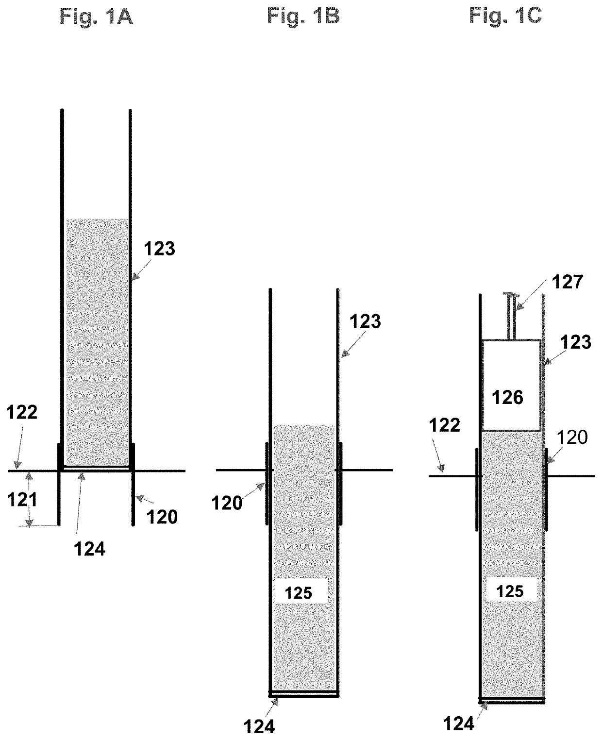
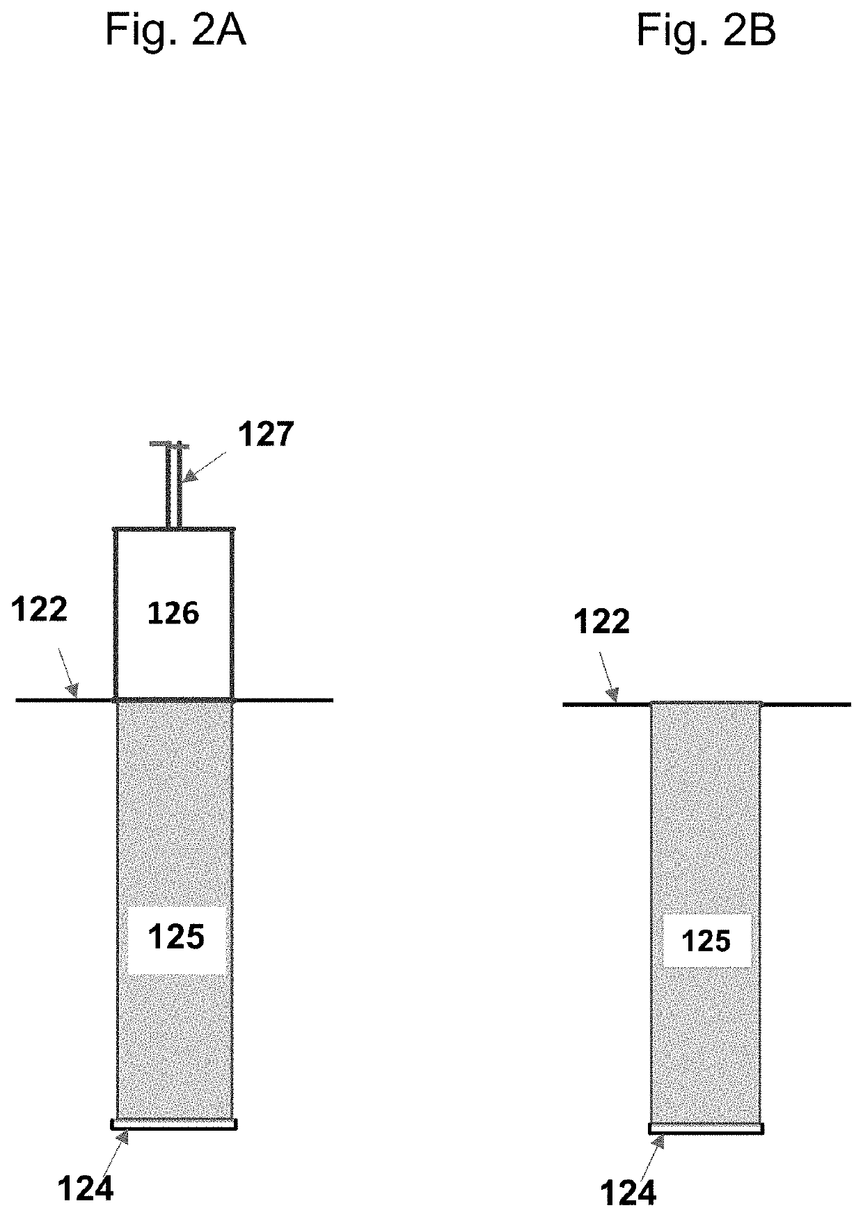
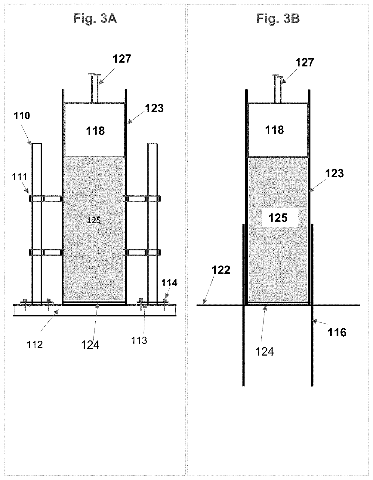
[0032]The main motivation for the invention of the rapid consolidation and compaction method (RCCM) is to develop a method for soil improvement which can densify a layer of the soil or the intermediate geomaterial (IGM) in a soil deposit. Cohesionless soils are defined as having N60 less than 50 blows / 0.3 m, whereas cohesionless Category 3 IGMs are defined as having N60 greater than 50 blows / 0.3 m (AASHTO, 2012). Cohesive soils are defined as having undrained shear strength less than 0.25 MN / m2, whereas cohesive IGMs Category 1 are defined as having undrained shear strength greater than 0.25 MN / m2 (AASHTO, 2012). The invention in this application comprises of a rapid consolidation and compaction method (RCCM) to produce rapid consolidation of the layer of clayey soil resulting in increase of its density and consistency. The RCCM comprises (i) first driving a hollow pipe section to some depth to minimize heave at the ground surface or above the layer of soil requiring improvement, (i...


PUM


Abstract

The rapid consolidation and compaction method comprises (i) first driving a hollow pipe, (ii) driving a pipe with a removable end plate after filling and compacting the sandy material in it, through the hollow pipe, to required depth, creating high excess pore-water pressures in the range of 50 to 300 KPa in clayey soils, (iv) pulling out the pipe section leaving behind the removable end plate and thereby installing porous displacement piles which allows dissipation of the excess pore-water pressures horizontally to the porous displacement pile, in which the excess water flows out vertically to the ground surface, and (v) the length of the drainage path is reduced to half the spacing between adjoining porous displacement piles, allowing rapid consolidation resulting in increase in density. Installing the porous displacement piles in the layer of loose to medium dense sand layer results in the instantaneous increase in its density.

Description

TECHNICAL FIELD[0001]This application is for applying for a utility patent in a technical field which includes civil engineering and geotechnical engineering for soil densification of layers of soils and intermediate geomaterials in a soil deposit. This specification / description is complete-in-itself. This invention is not sponsored or supported by federally sponsored research or development or by any other organization. This invention has been conceived, developed and completed independently by the inventor, Dr. Ramesh Chandra Gupta, Ph. D., P.E, President and Sole Owner of SAR6 INC. The inventor, Dr. Ramesh Chandra Gupta is a Citizen of the United States of America.BACKGROUND OF INVENTION[0002]Sand drain technique to strengthen the weak soils (Kennedy and Woods, 1954) has been in wide use from long time. Bowles, 1988 summarized the method of Sand Drains to strengthen and consolidate clayey soil layers which cannot support the load of the embankment or foundation structures. A circ...

Claims


Application Information

Patent Timeline
Patent Type & Authority Patents(United States)
IPC IPC(8): E02D5/24E02D27/16E02D7/02
CPCE02D5/24E02D7/02E02D27/16E02D2200/1685E02D2250/0007E02D2300/0079E02D3/08E02D3/106
Inventor GUPTA, RAMESH CHANDRA
Owner GUPTA RAMESH CHANDRA
Why Eureka
Try Eureka