Supercharge Your Innovation With Domain-Expert AI Agents!

Prosthetic tissue valves

a prosthetic tissue valve and valve body technology, applied in the field of prosthetic valves, can solve the problems of stenosis and insufficiency, heart failure, affecting organ function, etc., and achieve the effect of enhancing the structural integrity of the distal end region and enhancing the structural integrity of the prosthetic tissue valv

Active Publication Date: 2021-10-26
CORMATRIX CARDIOVASCULAR INC
View PDF6 Cites 0 Cited by
  • Summary
  • Abstract
  • Description
  • Claims
  • Application Information

AI Technical Summary

Benefits of technology

The invention relates to prosthetic tissue valves that have a distal end with a structural ring or stent structure to enhance their structural integrity. This helps to improve the functioning of the valves and ensure that they are durable and reliable.

Problems solved by technology

Stenosis and insufficiency can also occur concomitantly in the same valve or in different valves.
Both of the noted valve abnormalities can adversely affect organ function and result in heart failure.
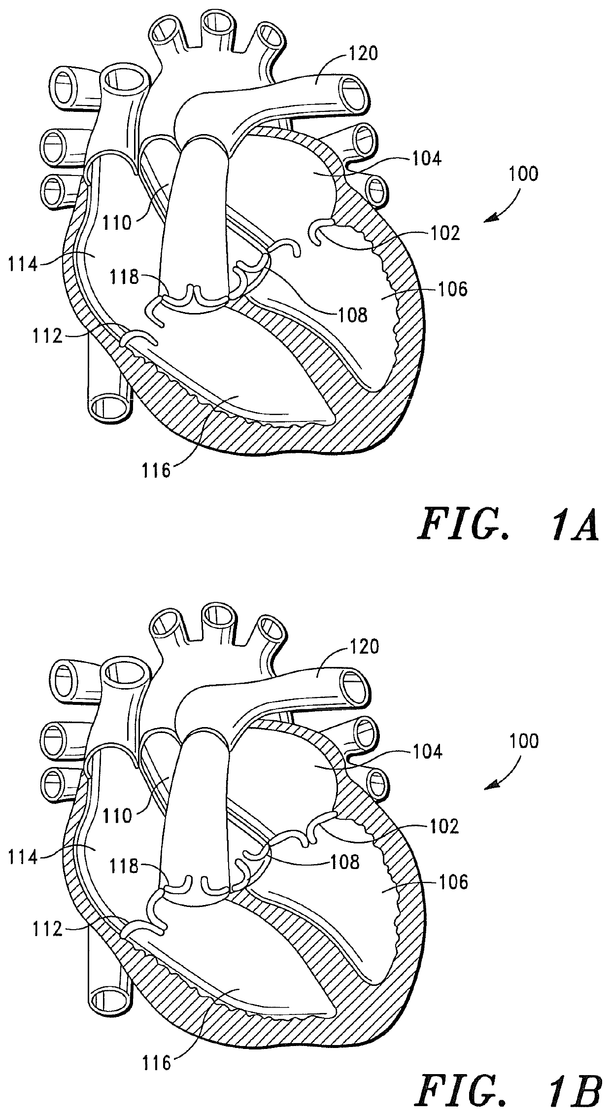
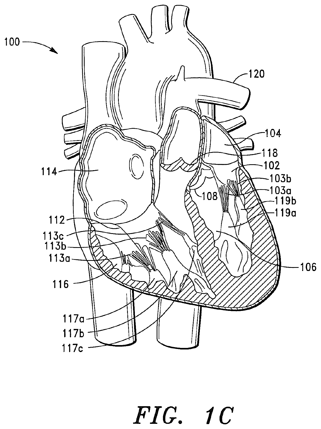
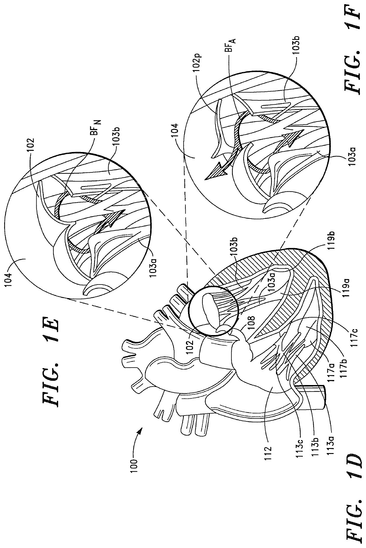
As illustrated in FIG. 1F, the regurgitated blood “BFA” flows back into the left atrium, which can, if severe, result in heart failure.
If such vegetation is present on the valves of the left side (i.e., the systemic circulation side) of the heart, embolization can, and often will, result in sudden loss of the blood supply to the affected body organ and immediate malfunction of that organ.
Likewise, bacterial or fungal vegetation on the tricuspid valve can embolize to the lungs.
The noted embolization can, and in many instances will, result in lung dysfunction.
A major problem associated with prosthetic valves is tissue valves with gluteraldehyde cross-linked leaflets will calcify and deteriorate over time.
Another problem is mechanical valves will require anticoagulation agents, such as Coumadin, which can cause side effects in high doses, such as uncontrolled bleeding.
Another problem is the valves do not remodel into normal tissue capable of regeneration and self-repair.
Another problem is many valves must be placed with open heart surgery while the patient is on a heart-lung machine.

Method used


Image

  • Prosthetic tissue valves
  • Prosthetic tissue valves
  • Prosthetic tissue valves

Examples


Embodiment Construction

[0070]Before describing the present invention in detail, it is to be understood that this invention is not limited to particularly exemplified apparatus, systems, structures or methods as such may, of course, vary. Thus, although a number of apparatus, systems and methods similar or equivalent to those described herein can be used in the practice of the present invention, the preferred apparatus, systems, structures and methods are described herein.

[0071]It is also to be understood that the terminology used herein is for the purpose of describing particular embodiments of the invention only and is not intended to be limiting.

[0072]Unless defined otherwise, all technical and scientific terms used herein have the same meaning as commonly understood by one having ordinary skill in the art to which the invention pertains.

[0073]Further, all publications, patents and patent applications cited herein are hereby incorporated by reference herein in their entirety.

[0074]As used in this specif...


PUM

PropertyMeasurementUnit
circumferenceaaaaaaaaaa
lengthaaaaaaaaaa
flow pressuresaaaaaaaaaa

Abstract

A prosthetic valve comprising a conical shaped ribbon structure comprising a polymeric composition. The ribbon structure comprises a plurality of elongated ribbon members that are positioned proximate each other in a joined relationship, wherein the ribbon members are positioned adjacent each other and form a plurality of fluid flow modulating regions that open when fluid flow through the valve exhibits a negative flow pressure and open when fluid flow through the valve exhibits a positive flow pressure.

Description

CROSS-REFERENCE TO RELATED APPLICATIONS[0001]This application is a continuation-in-part of U.S. application Ser. No. 16 / 440,504, filed on Jun. 13, 2019, which is a continuation-in-part of U.S. application Ser. No. 16 / 129,968, filed on Sep. 13, 2018, now U.S. Pat. No. 10,952,843, which is a continuation-in-part of U.S. application Ser. No. 15 / 206,833, filed on Jul. 11, 2016, now U.S. Pat. No. 10,188,510, which is a continuation-in-part application of U.S. application Ser. No. 14 / 960,354, filed on Dec. 5, 2015, now U.S. Pat. No. 9,907,649, which is a continuation-in-part application of U.S. application Ser. No. 14 / 229,854, filed on Mar. 29, 2014, now U.S. Pat. No. 9,308,084, which claims priority to U.S. Provisional Application No. 61 / 819,232, filed on May 3, 2013.FIELD OF THE INVENTION[0002]The present invention generally relates to prosthetic valves for replacing defective cardiovascular valves. More particularly, the present invention relates to prosthetic atrioventricular valves a...

Claims


Application Information

Patent Timeline
Patent Type & Authority Patents(United States)
IPC IPC(8): A61F2/24A61K31/165A61K31/4164A61K31/43A61K31/47A61K31/505A61K31/65A61K31/702A61K31/7028A61K31/7048A61K31/7056A61K38/14A61L27/18A61L27/58
CPCA61F2/2412A61K31/165A61K31/4164A61K31/43A61K31/47A61K31/505A61K31/65A61K31/702A61K31/7028A61K31/7048A61K31/7056A61K38/14A61L27/18A61L27/58A61F2220/0016A61F2230/005A61F2250/0067A61L27/3633A61F2230/0067A61L2430/20
Inventor MATHENY, ROBERT G
Owner CORMATRIX CARDIOVASCULAR INC
Features
  • R&D
  • Intellectual Property
  • Life Sciences
  • Materials
  • Tech Scout
  • Unparalleled Data Quality
  • Higher Quality Content
  • 60% Fewer Hallucinations
Learn More