Stator for a rotating electric machine having dielectric regions for a winding head board

a technology of dielectric regions and winding heads, which is applied in the direction of windings, winding insulation materials, cooling/ventilation arrangements, etc., to achieve the effects of reducing the space requirement improving the heat removal effect of the winding head board, and improving the thermal conductivity

Active Publication Date: 2021-11-02
SIEMENS AG
View PDF31 Cites 2 Cited by
  • Summary
  • Abstract
  • Description
  • Claims
  • Application Information

AI Technical Summary

Benefits of technology

[0021]In a further advantageous refinement, the at least one winding head board rests on a machine housing of the electrical rotating machine. The machine housing is produced, for example, from a metal material. As an alternative or in addition, heat which is created in the conductor tracks through which current flows can be dissipated by means of the machine housing, this leading to improved removal of heat from the winding head board.
[0022]The second dielectric material preferably has a higher thermal conductivity than the first dielectric material of the main body, wherein the region comprising the second dielectric material is arranged between at least one conductor track and the machine housing in such a way that heat can be transmitted between the at least one conductor track and the machine housing by means of the second dielectric material. Owing to an arrangement of this kind, the heat which is created in the conductor tracks through which current flows can be efficiently dissipated in the direction of the machine housing and/or the stator laminated core. Therefore, cooling ducts in the winding head board at least can be saved, as a result of which the space requirement for the winding head board is reduced, in particular in the axial direction.
[0023]The first dielectric material preferably has a higher mechanical strength than the second dielectric material and the thi

Problems solved by technology

Cooling ducts of this kind are required particularly when the thermal conductivity of the first dielectric materia

Method used


Image

  • Stator for a rotating electric machine having dielectric regions for a winding head board
  • Stator for a rotating electric machine having dielectric regions for a winding head board
  • Stator for a rotating electric machine having dielectric regions for a winding head board

Examples


first embodiment

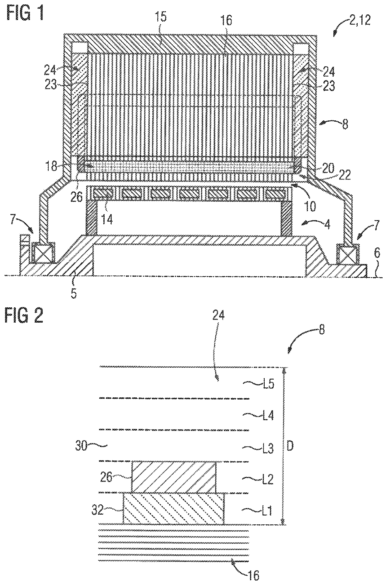
[0044]FIG. 2 shows an enlarged longitudinal section through a stator 8 of an electrical rotating machine 2 in the region of the winding head board 24 which is constructed, by way of example, from five layers L1, L2, L3, L4, L5. The thickness D of the entire winding head board 24 lies in the centimeter range, in particular in the range of from 3 to 10 cm. The first layer L1 of the winding head board 24 rests on the stator laminated core 15, so that the winding head board 24 is thermally connected to the stator laminated core 16. The topmost, by way of example fifth, layer L5 is optionally thermally connected to a further metal surface, for example a machine housing 15 which is illustrated in FIG. 1, so that the winding head board 24 is additionally thermally connected to the machine housing 15.

[0045]A conductor track 26 runs in the second layer L2. The layers L1, L2, L3, L4, L5 of the winding head board 24 are produced for the most part from a first dielectric material 30. In particu...

second embodiment

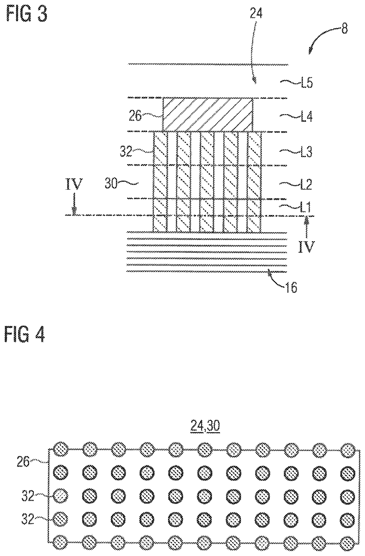
[0049]FIG. 3 shows an enlarged longitudinal section through a stator 8 of an electrical rotating machine 2 in the region of the winding head board 24. By way of example, a conductor track 26 is arranged in the fourth layer L4 of the winding head board 24. The region comprising the second dielectric material 32 is structured, in particular in the form of a plurality of, for example identical, pillars, arranged between the conductor track 26 and the stator laminated core 16, and constitutes, owing to the higher thermal conductivity and lower strength of the second dielectric material 32 in comparison to the first dielectric material 30, an optimum balance between thermal connection of the conductor track 26 to the stator laminated core 16 and strength of the winding head board 24. The further design of the stator 8 corresponds to the design in FIG. 2.

[0050]FIG. 4 shows an enlarged cross section through the second embodiment of the stator 8 in the region of the winding head board 24. T...

third embodiment

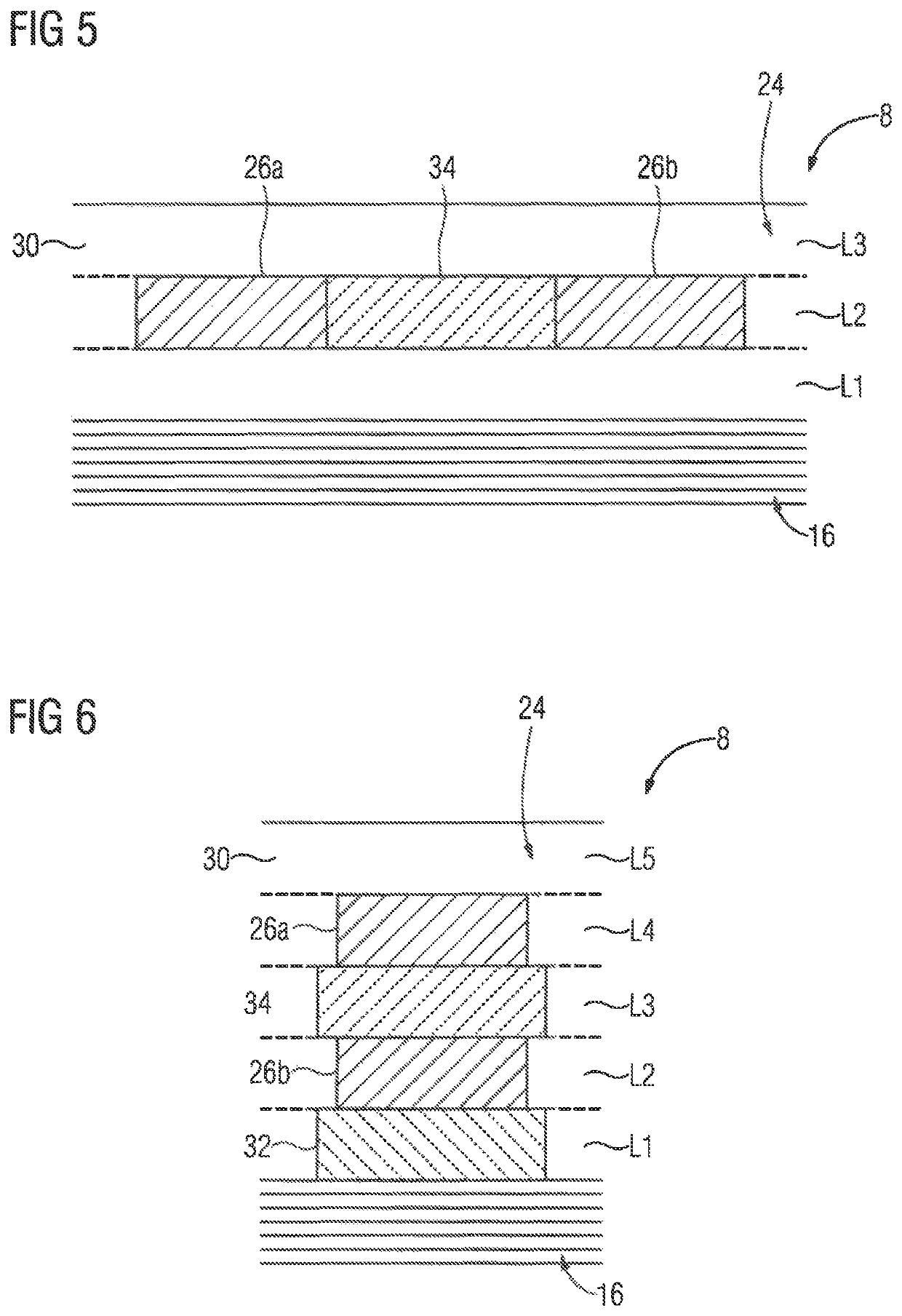
[0051]FIG. 5 shows an enlarged longitudinal section through a stator 8 of an electrical rotating machine 2 in the region of the winding head board 24 which has three layers L1, L2, L3. By way of example, two conductor tracks 26a, 26b run in the central, second layer L2. A region comprising a third dielectric material 34, which has a higher dielectric strength than the first dielectric material 30, is likewise located in the second layer between the two conductor tracks 26a, 26b. In particular, the third dielectric material 34 is embodied as a ceramic material. As an alternative, the third dielectric material 34 is embodied as a plastic with a high dielectric strength. Owing to the increased dielectric strength in the region between the two conductor tracks 26a, 26b, it is possible to reduce the distance between the conductor tracks. The further design of the stator 8 corresponds to the design in FIG. 2.


PUM


Abstract

A stator for an electrical rotating machine includes a laminated core having coil bars and a winding head board resting on an end side of the laminated core and having a main body including a first dielectric material. Conductor tracks are connected to the coil bars and integrated into the winding head board. The winding head board has a region with a second dielectric material and/or a region with a third dielectric material, with the second dielectric material having a higher thermal conductivity than the first dielectric material. The region with the second dielectric material is arranged between a conductor track and the laminated core such that heat is transmittable between conductor track and laminated core via the second dielectric material. The third dielectric material has a higher dielectric strength than the first dielectric material, with the region with the third dielectric material arranged between at least two conductor tracks.

Description

CROSS-REFERENCES TO RELATED APPLICATIONS[0001]This application is the U.S. National Stage of International Application No. PCT / EP2018 / 053661, filed Feb. 14, 2018, which designated the United States and has been published as International Publication No. WO 2018 / 153745 A1 and which claims the priority of European Patent Application, Serial No. 17157172.2, filed Feb. 21, 2017, pursuant to 35 U.S.C. 119(a)-(d).BACKGROUND OF THE INVENTION[0002]The invention relates to a stator for an electrical rotating machine.[0003]Furthermore, the invention relates to an electrical rotating machine comprising at least one stator of this kind.[0004]A stator of this kind is preferably found in an electrical rotating machine, in particular in a motor or generator, which has a power consumption of at least 1 megawatt.[0005]The stator windings of an electrical rotating machine of this kind are usually embodied as form-wound coils, which are also called bar-type coils. Form-wound coils are produced, for ex...

Claims


Application Information

Patent Timeline
IPC IPC(8): H02K9/22B33Y80/00H02K3/30H02K3/38H02K3/50
CPCH02K9/22B33Y80/00H02K3/30H02K3/38H02K3/50H02K2203/03H02K3/505H02K15/0081H02K9/223
Inventor SEWIOLO, BENJAMIN
Owner SIEMENS AG
Why Eureka
Try Eureka