Method for conducting optical measurement usingfull Mueller matrix ellipsometer

a mueller matrix and ellipsometer technology, applied in the field of optical measurement technology, can solve the problems of continuous increase of unknown variables to be measured, complex device structure, and limitations of ellipsometers, and achieve the effect of small error, more accurate parameters, and more accurate measurement results

Active Publication Date: 2021-11-30
BEIJING ARYHAU TECH CO LTD
View PDF8 Cites 0 Cited by
  • Summary
  • Abstract
  • Description
  • Claims
  • Application Information

AI Technical Summary

Benefits of technology

[0008]In order to solve the above problems, the present disclosure proposes a simplified method for conducting optical measurement with a full Mueller matrix ellipsometer whose calibration process is simplified.
[0023]The method for conducting optical measurement with a full Mueller matrix ellipsometer according to the present disclosure may utilize a reference sample which is isotropic and uniform, and obtain the phase retardation δ1 of the first phase compensator and the phase retardation δ2 of the second phase compensator based on the relation formulas between the light intensity data and the experimental Fourier coefficients as well as the polarization angle Ps of the polarizer and the polarization angle As of the analyzer which have been calibrated; and then obtains accurate values of all operating parameters (d, θ, Ps, As, Cs1, Cs2, δ1, δ2) of the full Mueller matrix ellipsometer by least square fitting according to the relation formulas between the theoretical Fourier coefficients and the operating parameters, with (d, θ, Ps, As, Cs1, Cs2, δ1, δ2) being as variables, and with the initial polarization angle Cs1 of the first phase compensator, the initial polarization angle Cs2 of the second phase compensator, the polarization angle Ps of the polarizer, the polarization angle As of the analyzer, the phase retardation δ1 of the first phase compensator, the phase retardation δ2 of the second phase compensator, which have been calibrated, being as initial values. The calibration method can take full advantages of measurement data obtained at a same time, which introduces relatively small error and obtains more accurate parameters after calibration. Thus, the result of measurement is more accurate when a sample to be tested is measured using the method of the present disclosure.

Problems solved by technology

With the advancement of the integrated circuit technology and the complexity of device structure, unknown variables to be measured are continuously increased, and traditional ellipsometers present certain limitations in various aspects, such as film thickness measurement of ultra-thin films, measurement of optical constants for anisotropic materials, depolarization analysis of surface features, and measurement of critical dimensions and topography in integrated circuits.
The ellipsometer may generate system deviation gradually during use as time goes on, especially a thickness of a wave plate is susceptible to changes in temperature and pressure as well as environmental deliquescence.
In this case, due to instability of mechanical structure and / or error in human operation, an error between an actual angle and an angle desired to be set may be caused, which easily leads to inaccuracy in the measurement of a reference sample.
Therefore, if this method is used, the accuracy in angle calibration of the polarizer is relatively low, and thus the measurement accuracy of the ellipsometer is limited.
The angle of incidence of light in an ellipsometer can be obtained by manual measurement, but the manual measurement has limited accuracy, and it is sometimes required to measure a reference sample at different angles of incidence to obtain more information thereof, the manual measurement is easy to lead to a wrong result of data analysis due to artificial adjustment error or reading error.
Chinese Patent No. 201010137774.0 discloses a device for automatically detecting an angle of incidence in an ellipsometry system, which can realize automatic detection of the angle of incidence, but the device requires position detecting devices to be installed at several places in the system, which makes systematic structure complicated.
Moreover, the calibration of the position detecting devices itself is also a complicated process, thus the application of such an automatic detecting device in an ellipsometer is limited.
During the mechanical loading and unloading processes, it cannot be guaranteed that loading position is the same as the previous loading position, which increases systematic error, and re-construction of the straight-through measuring system will increase workload.
It is required to remove two phase compensators during calibration and then put back, which increases systematic error.
Woollam's ellipsometer as shown in FIG. 3, the incident arm is rotated from position 1 to position 3 during calibration, and the exiting arm is rotated from position 2 to position 4), which increases the complexity of the system.
These methods increase the complexity of the system and the calibration process is more complicated.
Since a method for conducting optical measurement with a full Mueller matrix ellipsometer is performed after the calibration of the full Mueller matrix ellipsometer, the complexity in the calibration process of the full Mueller matrix ellipsometer must result in the complexity of the method for conducting optical measurement with a full Mueller matrix ellipsometer.

Method used


Image

  • Method for conducting optical measurement usingfull Mueller matrix ellipsometer
  • Method for conducting optical measurement usingfull Mueller matrix ellipsometer
  • Method for conducting optical measurement usingfull Mueller matrix ellipsometer

Examples


embodiment 1

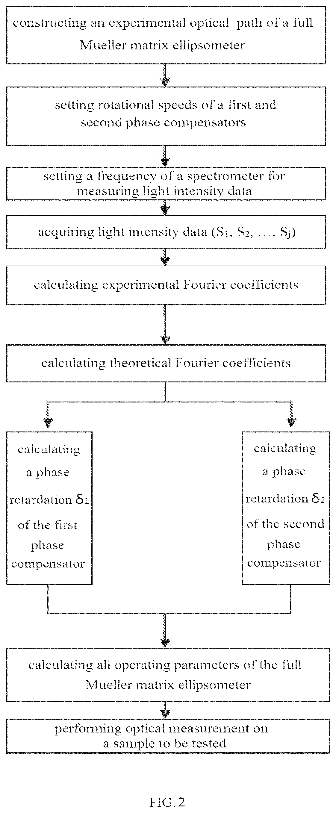
[0028]A method for conducting optical measurement with a full Mueller matrix ellipsometer according to Embodiment 1 of the present invention may comprise the following steps:

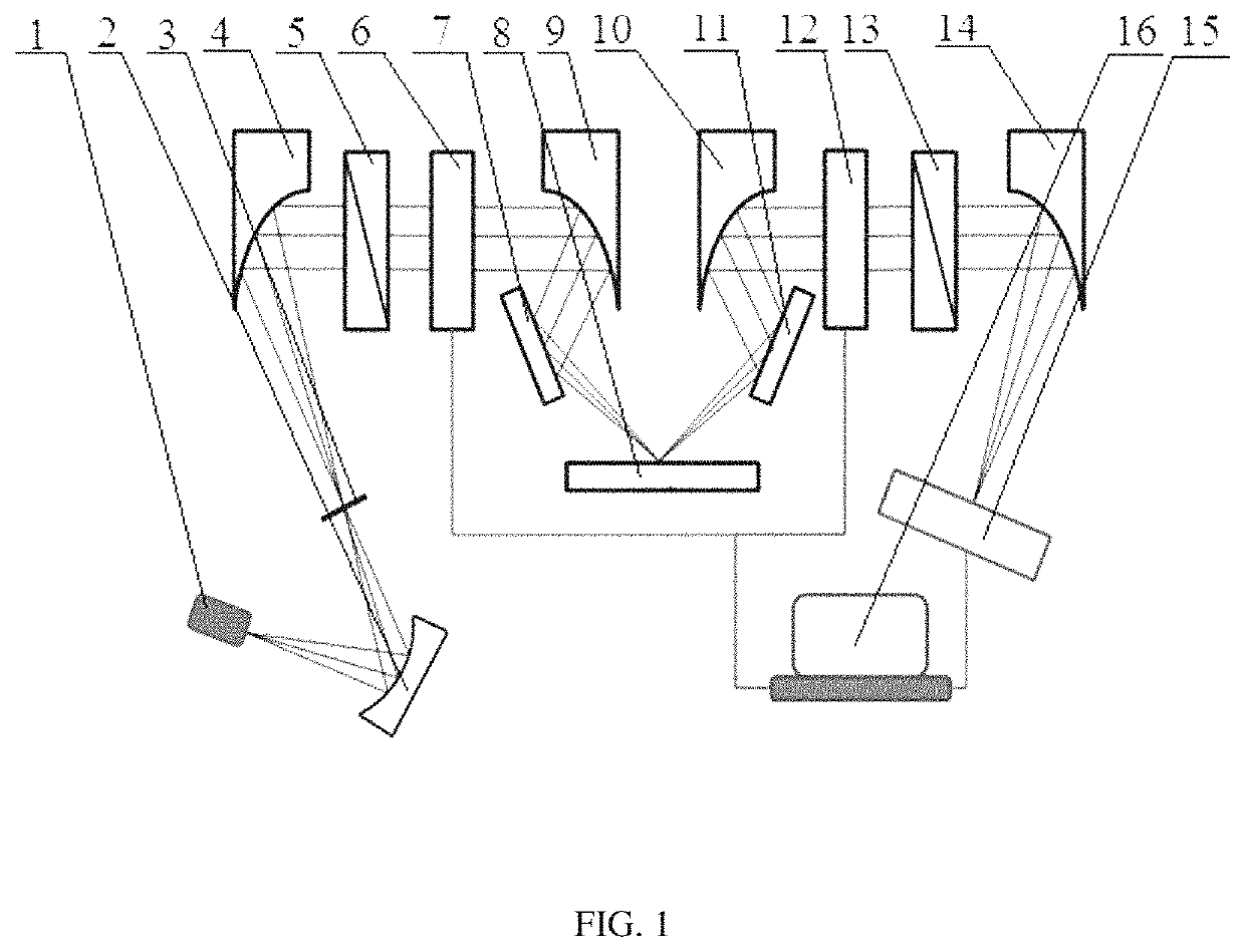
[0029]step 1: referring to FIG. 1, constructing an experimental optical path of a full Mueller matrix ellipsometer. The experimental optical path may include a light source 1, an annular mirror 2, a pinhole 3, a first off-axis parabolic mirror 4, a polarizer 5, a first phase compensator 6, a first plane mirror 7, a sample stage 8, a second off-axis parabolic mirror 9, a third off-axis parabolic mirror 10, a second plane mirror 11, a second phase compensator 12, an analyzer 13, a fourth off-axis parabolic mirror 14, a spectrometer 15 and a terminal 16. An isotropic and uniform reference sample is carried on the sample stage 8. The experimental optical path of the full Mueller matrix ellipsometer, which can be self-calibrated through total regression, may have the following optical process:

Sout=MAR(A′)R(−C2)Mc2(δ2...

embodiment 2

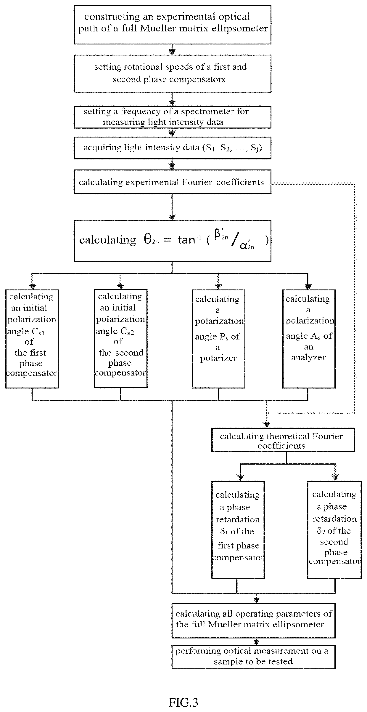
[0076]Referring to FIG. 3, the difference between the total regression self-calibrated full Mueller matrix ellipsometer according to the embodiment 2 of the present invention and the total regression self-calibrated full Mueller matrix ellipsometer according to the embodiment 1 of the present invention lies in that: the total regression self-calibration method of the total regression self-calibrated full Mueller matrix ellipsometer according to the embodiment 2 of the present invention may further comprise the following steps:

[0077]obtaining respective θ2n based on respective experimental Fourier coefficients α′2n, β′2n, where θ2n is an intermediate parameter defined for the convenience of calculation;

[0078]obtaining an initial polarization angle Cs1 of a first phase compensator based on the respective θ2n;

[0079]obtaining an initial polarization angle Cs2 of a second phase compensator based on the respective θ2n;

[0080]obtaining a polarization angle Ps of a polarizer based on the res...


PUM

PropertyMeasurementUnit
optical measurementaaaaaaaaaa
optical pathaaaaaaaaaa
rotational speedsaaaaaaaaaa

Abstract

A method for conducting optical measurement using a full Mueller matrix ellipsometer, which belongs to the technical field of optical measurements. The optical measurement method comprises: constructing an experimental optical path of a full Mueller matrix ellipsometer; conducting complete regression calibration on the full Mueller matrix ellipsometer; placing a sample to be measured on a sample platform, and obtaining an experimental Fourier coefficient of the sample to be measured; and according to the experimental Fourier coefficient of the sample to be measured, obtaining information about the sample to be measured. Since a calibration method for the full Mueller matrix ellipsometer is not only simple in operation process, but also makes full use of data of the full Mueller matrix ellipsometer measured at the same time, the introduced error is relatively small and the parameter obtained by calibration is more accurate, so that the measurement result is more accurate when the sample to be measured is measured. Thus, the process of the optical measurement method is simplified.

Description

TECHNICAL FIELD[0001]The present disclosure relates to the field of optical measurement technology, and more particularly to a method for conducting optical measurement with a full Mueller matrix ellipsometer.BACKGROUND OF THE INVENTION[0002]An ellipsometer is an optical measuring instrument that takes advantage of the polarization characteristics of light to acquire information of a sample to be tested. The working principle of the ellipsometer is as below: letting light passing through a polarizer be incident on a sample to be tested; obtaining the information of the sample to be tested by measuring a change of polarization state (amplitude ratio and phase difference) of an incident light and a reflected light on a surface of the sample to be tested. The ellipsometer with rotatory polarizer or single rotatory compensator can obtain up to 12 parameters of the sample in one measurement. With the advancement of the integrated circuit technology and the complexity of device structure,...

Claims


Application Information

Patent Timeline
Patent Type & Authority Patents(United States)
IPC IPC(8): G01N21/21G01N21/27
CPCG01N21/211G01N21/274G01N2021/213G01N2201/127
Inventor LIU, TAOCUI, GAOZENGLI, GUOGUANGXIONG, WEIWEN, LANGFENG
Owner BEIJING ARYHAU TECH CO LTD
Why Eureka
Try Eureka