Securing a second object to a first object

a technology for securing a second object and a first object, applied in the field of mechanical engineering and construction, can solve the problems of increasing manufacturing costs, no long-term control of reliability, new challenges in the bonding element of these materials, etc., and achieve the effect of efficient and quick

Active Publication Date: 2021-12-21
WOODWELDING
View PDF16 Cites 0 Cited by
  • Summary
  • Abstract
  • Description
  • Claims
  • Application Information

AI Technical Summary

Benefits of technology

[0006]It is therefore an object of the present invention to provide a method of mechanically securing a second object to a first object, the method overcoming disadvantages of prior art methods. Especially, it is an object of the present invention to provide a method of mechanically securing a second object to a first object to yield a mechanical bond that is mechanically stable and resistant especially to shearing forces so that the method is suitable for securing reinforcement to a planar object. Further, it is an object of the present invention to provide a method of mechanically securing a second object to a first object, which method has the potential of being low-cost, efficient and quick.
[0036]The step of causing the flow portion to flow may include causing at least parts of the protruding section to become embedded in material of the flow portion. Embedding does not necessarily imply that the flow portion is fully surrounded. Rather, the flow portion after re-solidification will at least to some extent a deformation (back) of the protruding section. The effect is that when a shearing force acts on the connection between the first and second objects, the protruding section will prevent a relative movement, and the thermoplastic material will prevent a giving way by the protruding section.
[0037]An effect of the approach according to the invention is that the achieved connection provides some resistance against axial relative forces on the first and second objects (against forces trying to pull them apart) and provides a very strong resistance against shear forces acting between the first and second objects in that the material of the connector impedes any bending of the protruding section back into its initial position. Even if the thermoplastic material of the connector itself may have a limited mechanical strength, the resistance against such shear forces (in-plane relative forces) may be very strong due to the intrinsic strength of the materials of the first object (or the building layer thereof penetrated by the protruding section) and of the second object and due to the fact that these materials are interlocked in the resulting configuration.
[0062]For applying a counter force to the pressing force, the first object may be placed against a support, for example a non-vibrating support. According to a first option, such a support may include a supporting surface vis-à-vis the spot against which the connector is pressed, i.e. distally of this spot. This first option may be advantageous because the bonding can be carried out even if the first object by itself does not have sufficient stability to withstand the pressing force without substantial deformation or even defects. However, according to a second option, the distal side of the first object may be exposed, for example by the first object being held along the lateral sides or similar. This second option features the advantage that the distal surface will not be loaded and will remain unaffected if the second object does not reach to the distal side.

Problems solved by technology

The new materials cause new challenges in bonding elements of these materials—especially in bonding flattish object to an other object.
Adhesive bonds can be light and strong but suffer from the disadvantage that there is no possibility to long-term control the reliability, since a degrading adhesive bond, for example due to an embrittling adhesive, is almost impossible to detect without entirely releasing the bond.
Also, adhesive bonds may lead to a rise in manufacturing cost, both, because of material cost and because of delays caused in manufacturing processes due to slow hardening processes, especially if the surfaces to be connected to each other have certain roughness and as a consequence the quickly hardening thin-layer adhesives cannot be used.

Method used


Image

  • Securing a second object to a first object
  • Securing a second object to a first object
  • Securing a second object to a first object

Examples


Embodiment Construction

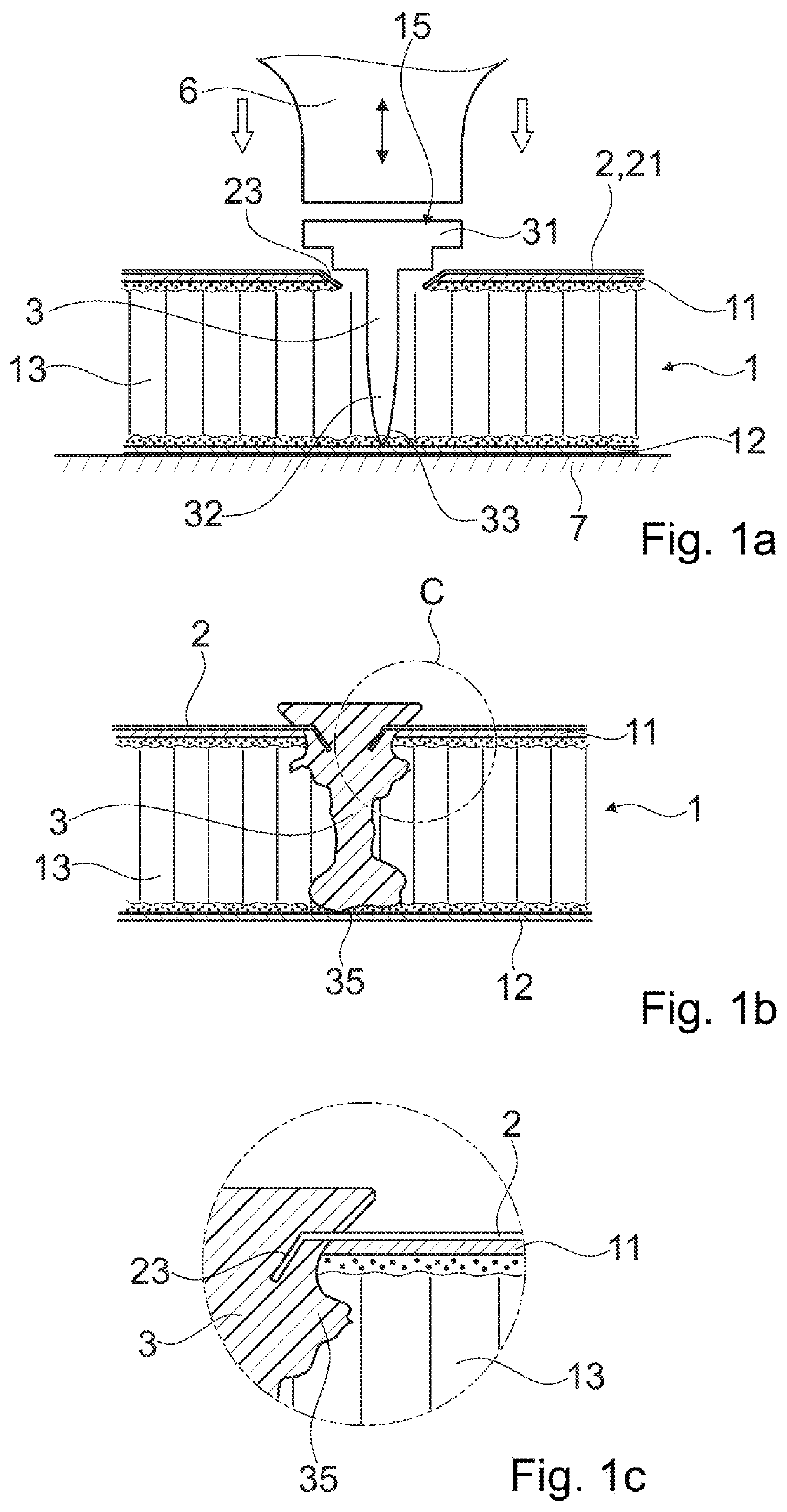
[0100]The configuration of FIG. 1a includes a first object 1 being a sandwich board with a first building layer 11, a second building layer 12, and an interlining 13 between the building layers. The first and second building layers may include a fiber composite, such as a continuous glass or continuous carbon fiber reinforced resin. The interlining may be any suitable lightweight material, for example a honeycomb structure of cardboard. An additional adhesive may bond the building layers 11, 12 to the interlining. In an example a slightly foaming adhesive on polyurethane basis is used. Possible pores in the adhesive may contribute to the anchoring in the various embodiments of the invention. The face that in the depicted orientation is the upper face serves as attachment face for the second object 2.

[0101]The first object includes an opening 15 that extends from the attachment face inwards and especially goes through the first building layer.

[0102]A second object 2 has a sheet porti...


PUM

PropertyMeasurementUnit
sizeaaaaaaaaaa
temperaturesaaaaaaaaaa
glass transition temperatureaaaaaaaaaa

Abstract

A method of bonding a second object to a first object includes: providing the first object, which includes a thermoplastic liquefiable material in a solid state; providing the second object, which includes a surface portion that has a coupling structure with an undercut such that the second object can make a positive-fit connection with the first object; and pressing the second object against the first object with a tool that is in physical contact with a coupling-in structure of the second object while mechanical vibrations are coupled into the tool. The step of pressing and coupling vibrations into the tool continues until a flow portion of the thermoplastic material of the first object is liquefied and flows into the coupling structures of the second object. Thereafter, the thermoplastic material of the first object is permitted to re-solidify to yield a positive-fit connection between the first and second objects.

Description

BACKGROUND OF THE INVENTIONField of the Invention[0001]The invention is in the fields of mechanical engineering and construction, especially mechanical construction, for example automotive engineering, aircraft construction, shipbuilding, machine construction, toy construction etc. In particular, it relates to a method of—mechanically—securing a second object to a first object.Description of Related Art[0002]In the automotive, aviation and other industries, there has been a tendency to move away from steel-only constructions and to instead use lightweight material such as aluminum or magnesium metal sheets or polymers, such as carbon fiber reinforced polymers or glass fiber reinforced polymers or polymers without reinforcement, for example polyesters, polycarbonates, etc.[0003]An example of new building material elements are lightweight building elements that include two outer, comparably thin building layers, for example of a fiber composite, such as a glass fiber composite or carb...

Claims


Application Information

Patent Timeline
Patent Type & Authority Patents(United States)
IPC IPC(8): B29C65/08B29C65/60B29C65/00F16B5/04F16B5/01F16B3/00B29C65/74B29C65/06F16B17/00B29K101/12B29K105/00B29L9/00B29L31/30
CPCB29C65/603B29C65/08B29C66/0222B29C66/02242B29C66/1122B29C66/3022B29C66/30321B29C66/30325B29C66/472B29C66/474B29C66/721B29C66/723B29C66/7254B29C66/72525B29C66/7392B29C66/742B29C66/81427B29C66/8322B29C66/92445B29C66/92921B29C66/9517F16B3/005F16B5/01F16B5/04B29C65/06B29C65/7437B29C66/71B29C66/727B29C66/7212B29C2793/0045B29K2101/12B29K2105/253B29L2009/003B29L2031/30F16B17/008B29K2307/04B29K2309/08B29K2067/00B29K2069/00
Inventor MAYER, JÖRGKVIST, JOAKIM
Owner WOODWELDING
Why Eureka
Try Eureka