

Effective coupling coefficients for strained single crystal epitaxial film bulk acoustic resonators
a single crystal epitaxial film and effective coupling coefficient technology, applied in piezoelectric/electrostrictive/magnetostrictive devices, piezoelectric/electrostrictive/magnetostrictive devices, electrical apparatus, etc., can solve the problems of achieving power handling requirements and unacceptable in many telephony applications, and achieve the effect of reducing leakage of 1510 mhz signals and enhancing the performance of arrays of acousti
- Summary
- Abstract
- Description
- Claims
- Application Information
AI Technical Summary
Benefits of technology
Problems solved by technology
Method used
Image

Examples
Embodiment Construction
[0042]The present invention relates generally to acoustic resonators and more particularly to controlling the effective coupling coefficient of a single crystal epitaxial acoustic resonator.
[0043]With reference to FIG. 4, a transmit band-pass filter 68 is shown schematically as including four series FBARs 70, 72, 74 and 76 connected in electrical series from a transmit port 78 to an antenna port 80. The filter also includes two shunt FBARs 82 and 84. The first shunt FBAR 82 is connected between the two pairs of series FBARs, while the second shunt FBAR 84 is connected between the antenna port and the series FBAR 76. FIG. 4 also shows one stage of a receive filter 73. This stage includes a series FBAR 75 and a shunt FBAR 77. The number of stages in a transmit (Tx) filter or a receive (Rx) filter is not critical to the invention that will be described more fully below. The significance of the filters is that at least one FBAR will have an effective coupling coefficient that is intenti...
PUM
| Property | Measurement | Unit |
|---|---|---|
| center frequency | aaaaa | aaaaa |
| frequencies | aaaaa | aaaaa |
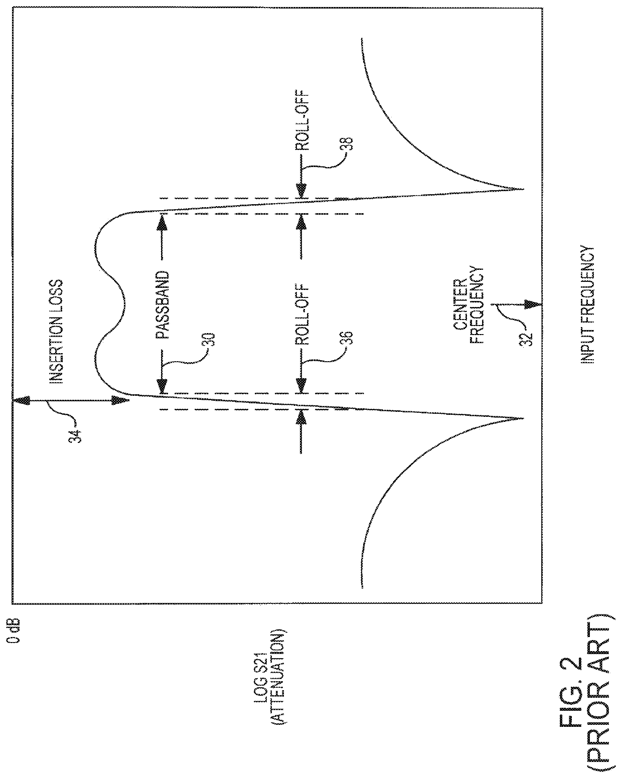
| insertion loss | aaaaa | aaaaa |
Abstract
Description
Claims
Application Information