Controlled irradiation of an object

a controlled irradiation and object technology, applied in the field of controlled irradiation of objects, can solve the problems of difficult to achieve and difficulty in achieving uniform or precise radiation dose over the entire surface of the tissue, so as to achieve more uniform irradiation and avoid excessive damage to surrounding healthy tissue or other materials.

Active Publication Date: 2022-01-11
SIEMENS HEALTHCARE GMBH
View PDF12 Cites 0 Cited by
  • Summary
  • Abstract
  • Description
  • Claims
  • Application Information

AI Technical Summary

Benefits of technology

[0009]In the present embodiments, the effect whereby an optically observable property of a first substance that has been added beforehand to the object that is to be irradiated is changed due to exposure to radiation (e.g., due to exposure to visible, infrared, or ultraviolet light) or due to exposure to an ionizing radiation is exploited. A detector system captures light being emitted from the object in order to detect the optically observable property, to determine the change in the optically observable property, and, based thereon, to calculate a value for the dose.
[0109]In this case, the optically observable property of the at least one further substance may correspond to the reflectance spectrum of the further material. The reflectance spectrum of the further material may, for example, be invariable when exposed to and irradiated with the ionizing radiation. This enables a particularly reliable reference value to be determined based on the reflectance spectrum of the further material. This reference value may be used, for example, for accurately determining the dose using the change in the reflectance spectrum of the first material.

Problems solved by technology

With known methods, it may be problematic or difficult to achieve a uniform or precise radiation dose over the entire surface of the tissue that is to be irradiated.
For example, it is problematic if the tissue regions containing tumor cells are not irradiated or are irradiated with too little dose, or if healthy tissue is irradiated with an unnecessarily strong dose.
In one embodiment, when a movement of the tissue (e.g., the organ) occurs during the irradiation, due, for example, to the breathing of the patient, the dose may fluctuate in an undesirable manner.
Similar problems are encountered here also.

Method used


Image

  • Controlled irradiation of an object

Examples


Embodiment Construction

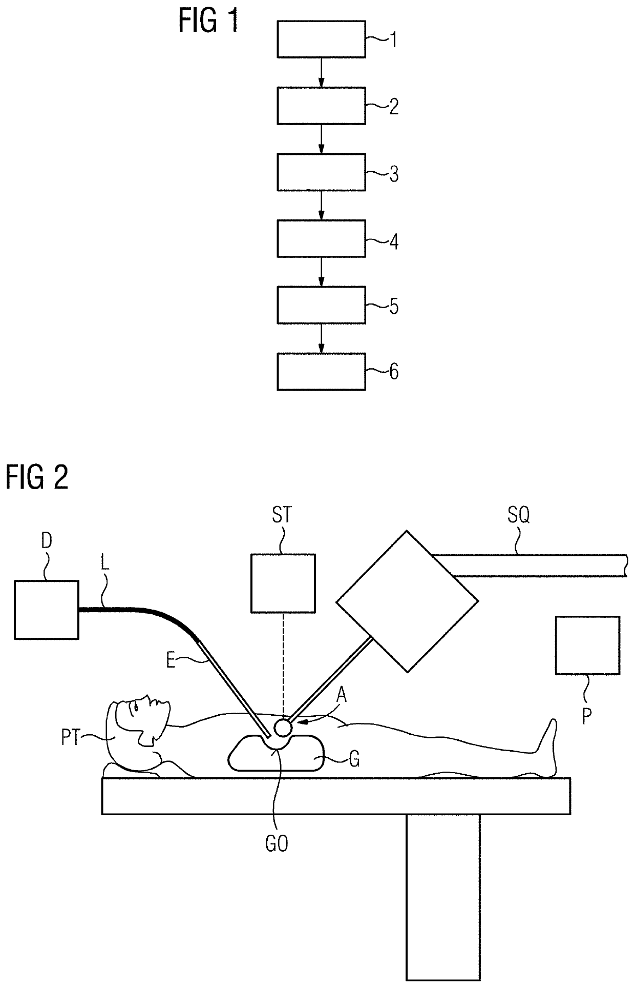
[0134]FIG. 1 is a schematic representation of one embodiment of a method with the aid of a flowchart.

[0135]Following a tumor resection, an intraoperative radiation therapy is to be performed in order to kill tumor cells that have infiltrated into healthy tissue.

[0136]In act 1 of the method, a first substance having a variable optically observable property (e.g., a first fluorescent dye) is added to a tissue that is to be irradiated. This may be accomplished, for example, by administering the first fluorescent dye to the patient (e.g., orally or intravenously). The first fluorescent dye is then, for example, accumulated specifically in the tumor cells. A dye with the designation 5-ALA / PPIX, which is employed, for example, in the treatment of brain tumors or glioblastomas, may be used, for example, as the first fluorescent dye (e.g., for fluorescence-guided surgery). Alternatively, following completion of the tumor resection, the first substance (e.g., the first fluorescent dye) may b...


PUM

PropertyMeasurementUnit
excitation wavelengthaaaaaaaaaa
fluorescentaaaaaaaaaa
fluorescenceaaaaaaaaaa

Abstract

In order to achieve improved dose control, a device for irradiating an object having an optically observable property is provided. The device includes an applicator for irradiating the object, and a detector system that is configured to capture light being emitted from an irradiated region and, based thereon, to generate a detector signal. A processor unit is configured to calculate a value for the property based thereon and, based on the calculated value, to determine a dose for the irradiation.

Description

[0001]This application claims the benefit of German Patent Application No. DE 10 2019 201 970.6, filed Feb. 14, 2019, and German Patent Application No. DE 10 2019 206 618.6, filed May 8, 2019, which are incorporated by reference in their entirety.BACKGROUND[0002]The present embodiments relate to controlled irradiation of an object to which a substance having an optically observable property has been added.[0003]In intraoperative radiation therapy, a tumor resection is performed, followed by an application of an ionizing radiation to the tissue adjoining the previously removed tumor. In this way, it is aimed, for example, to kill tumor cells that have infiltrated into the healthy tissue directly by a high radiation dose, while the deeper-lying tissue receives only a low dose. Applications include, for example, tumors in the brain, in the ear, nose, and throat tract, in the abdomen, in the pelvis, in the spinal column, in the skin, or in the breast.[0004]In known methods, use is made,...

Claims


Application Information

Patent Timeline
Patent Type & Authority Patents(United States)
IPC IPC(8): A61N5/10G01N21/64A61B5/00
CPCA61N5/1071A61B5/0036A61B5/0071G01N21/645G01N21/6486A61B2576/00A61N2005/1074A61N2005/1087A61N2005/1089G01N2021/6463A61N5/1015A61N2005/0628A61B5/0084A61L2/10
Inventor REGENSBURGER, ALOIS
Owner SIEMENS HEALTHCARE GMBH
Why Eureka
Try Eureka