

Circulatory assistance device
a technology of circulatory assistance and heart valve, which is applied in the direction of circulatory assistance devices, intravenous devices, blood pumps, etc., can solve the problems of inability to compensate for weak heart pumping power, inability to choose management options in cases of impaired cardiac function, and inability to have other than heart transplantation adequate treatment, etc., to achieve simple design and high efficiency
- Summary
- Abstract
- Description
- Claims
- Application Information
AI Technical Summary
Benefits of technology
Problems solved by technology
Method used
Image

Examples
first embodiment
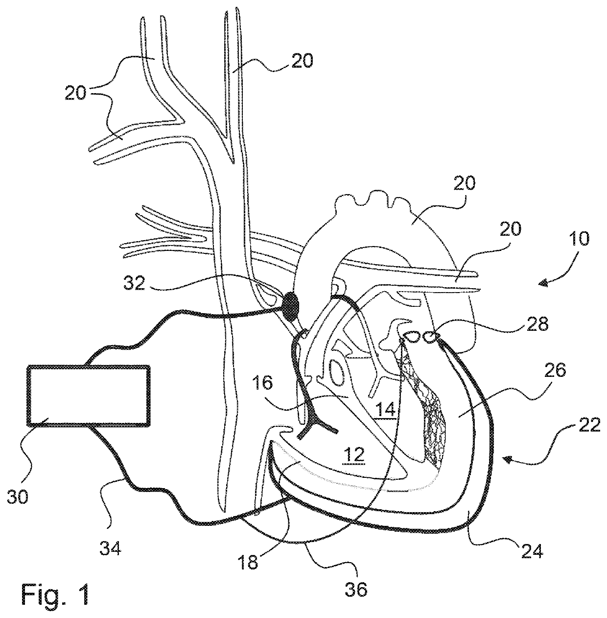
[0042]A cuff 22 of a circulatory assistance device in a first embodiment fits closely around the heart 10 during the diastolic phase of the cardiac cycle. The cuff includes an outer contraction layer 24 and an inner padding layer 26. In the interior of the contraction layer 24 there is at least one elastic elastomer membrane, which preferably has a closed annular shape, or as shown in FIGS. 1 and 2, a tulip shape. In the cuff 22, several dielectric elastomer membranes may be arranged adjacent to or one on top of the other. The elastomer membranes are preferably closed, but within the scope of the invention it is also possible to arrange several separately controlled annular elastomer membranes alongside one another.
[0043]Materials that may be considered for the contraction layer 24 include, for example, PDMS, polyurethane, and acrylates (e.g., VHB from 3M). Particularly suitable is a silicone with polydimethyl siloxane as the polymer component and acrylic polymers and natural rubber...
second embodiment
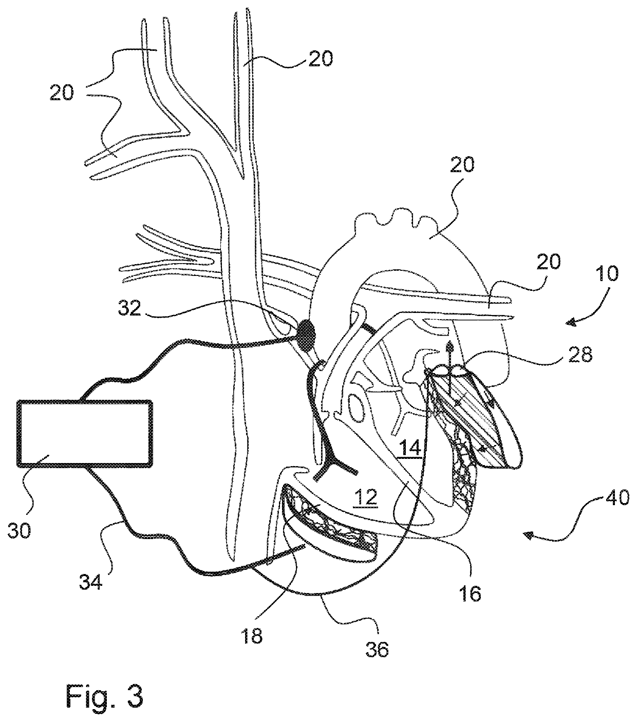
[0047]In FIG. 3, a circulatory assistance system in the form of an annular cuff 40 is shown. Aside from the fact that this cuff 40 does not surround the apex of the heart 10, this has structurally and functionally the same design as the cuff 22.
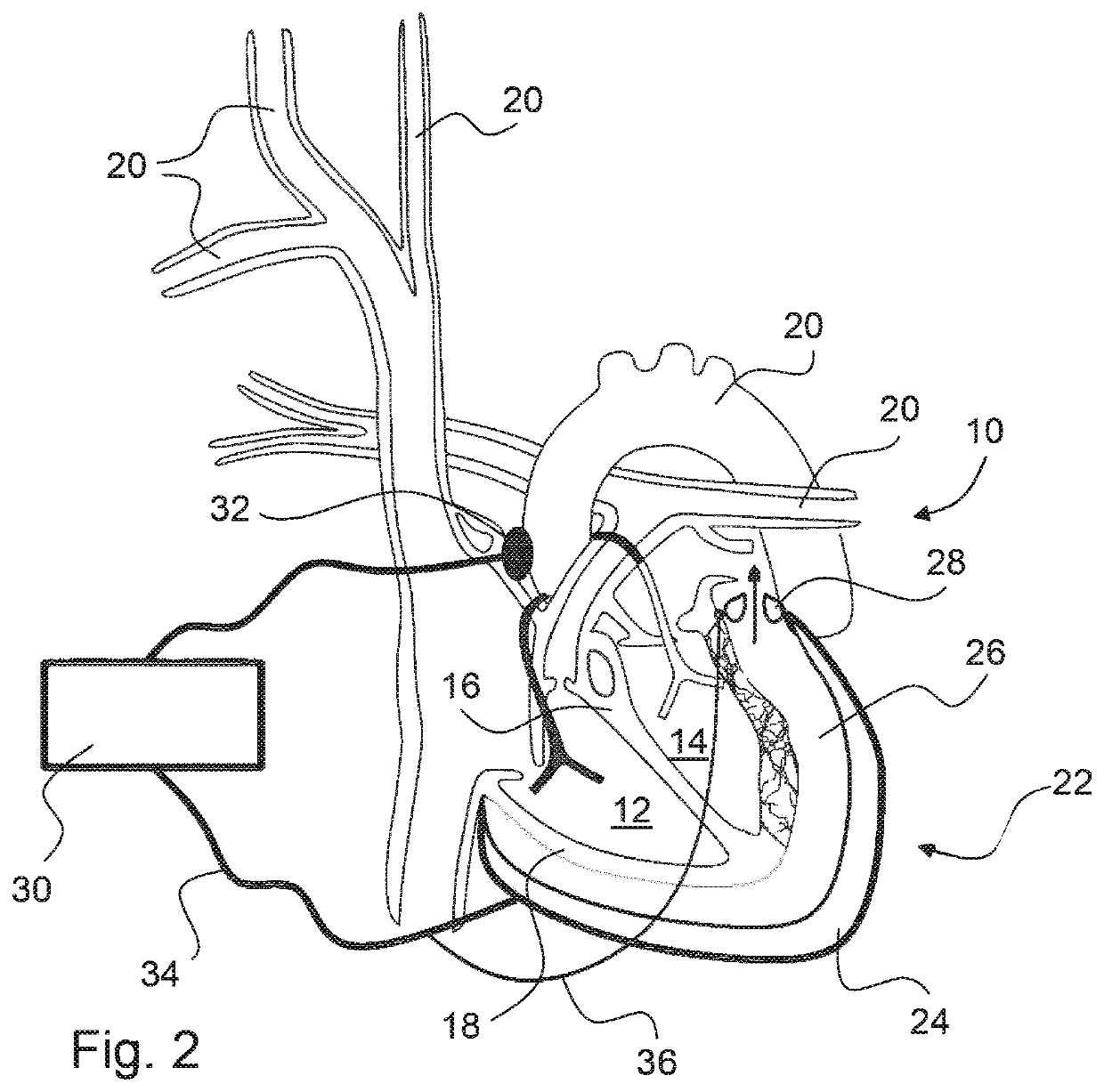
[0048]As can be seen in FIGS. 1 to 3, the cuff 22 or 40 preferably extends along the entire ventricular wall 18 and is fastened to it by means not shown, preferably mounted in an annular shape.
[0049]In normal operation the sensor 32 detects the cardiac cycle of the heart 10. In an initial state the heart 10 is in the diastolic phase, in which it is relaxed and occupies the largest volume, wherein the two ventricles fill with blood. In this state the contraction layer 24 is supplied with power so that this is in the state of greatest possible expansion. The padding layer 26 filled with an incompressible fluid at this time is located internally against the ventricular wall 18 and externally against the contraction layer 24. As soon as the contr...
third embodiment
[0051]In FIG. 4, a third embodiment is shown, which differs from the previous embodiments in that the contraction layer 24 includes a number of adjacent annular sections 41, each of which is individually controlled by the control device 30, which for the sake of clarity is only shown for the annular section marked with reference symbol 41′. This is normally a film that is subdivided into rings. Alternatively, individual film rings connected together may be provided.
[0052]Correspondingly, the padding layer 26 located beneath it is subdivided into a number of adjacent annular regions 44 separated by expandable partitions 42. Each annular region 44 has its own outlet valve 46, controlled by the control device 30 (for the sake of clarity, only shown here for one outlet valve 46′) into the environment.
[0053]The annular sections 41 are separately supplied with power by the control device 30 in a time-staggered sequence, synchronous with the cardiac contraction spreading from the cardiac a...
PUM
 Abstract
Description
Claims
Application Information