Multi-tube pyrolysis system for waste plastic

a pyrolysis system and waste plastic technology, applied in the direction of educts, chemistry apparatus and processes, products, etc., can solve the problems of high labor cost, waste plastic decomposition waste plastic decomposition oil in a small quantity, etc., and achieve the effect of reducing sulfur oxide (sox)

Active Publication Date: 2022-02-01
LEE YUNG TENG +1
View PDF4 Cites 0 Cited by
  • Summary
  • Abstract
  • Description
  • Claims
  • Application Information

AI Technical Summary

Benefits of technology

[0005]The primary aspect of the present invention is to provide a multi-tube pyrolysis system for waste plastic which is capable of recycling waste plastic to serve as a fuel of heat source and acquiring recyclable resources (such as decomposed oil and syngas), and the multi-tube pyrolysis system contains a cooling module and a filtration module so as to filter nitrogen oxides (NOx) and sulfur oxides (SOx) from smoked gases produced after thermal degradation of the waste plastic, thus eliminating particles of the smoked gases.
[0006]Another aspect of the present invention is to provide a multi-tube pyrolysis system for waste plastic which is capable of decomposing the waste plastic after feeding the waste plastic successively so as to produce heat source, thus saving labor cost, obtaining mass production, and reducing fabrication cost.
[0012]Preferably, a secondary combustion chamber assembly supplies heat source to the plastic extrusion module so that a temperature of the output tube of the plastic extrusion module is within 250° C. to 300° C. so as to preheat the waste plastic and to eliminate moisture of the waste plastic.
[0018]Preferably, the smoked gases are guided into a cooler to reduce a temperature of the smoked gases to 200° C., and the smoked gases are sprayed by alkali adding equipment so as to eliminate sulfur oxide (SOx).

Problems solved by technology

For example, it takes more than 10 hours to decompose the waste plastic.
In addition, the decomposed oil is decomposed from the waste plastic in a small quantity and high labor cost.

Method used


Image

  • Multi-tube pyrolysis system for waste plastic
  • Multi-tube pyrolysis system for waste plastic
  • Multi-tube pyrolysis system for waste plastic

Examples


Embodiment Construction

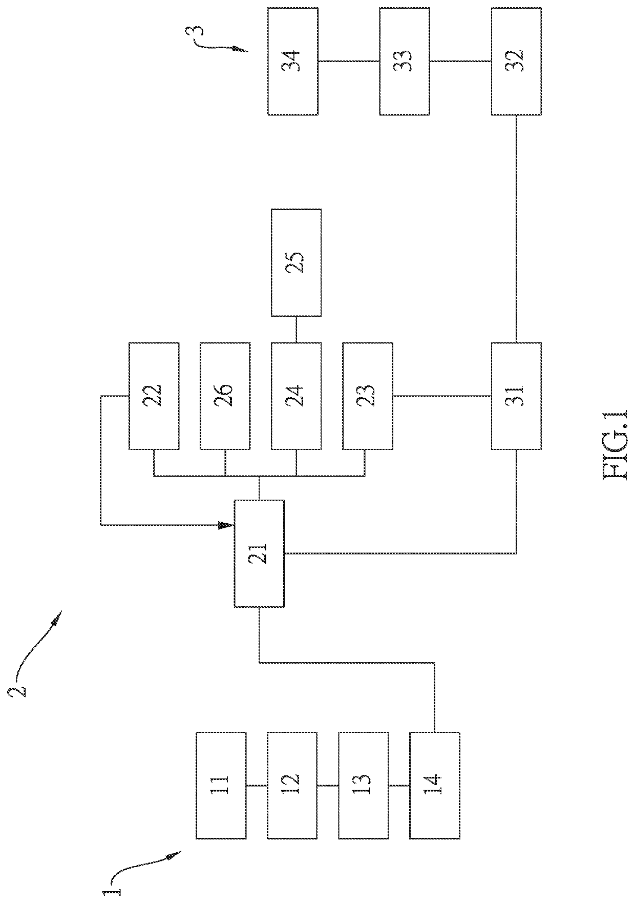
[0026]With reference to FIGS. 1-7, a multi-tube pyrolysis system for waste plastic according to a preferred embodiment of the present invention comprises: a preparation system 1, a decomposition system 2, and a filtration system 3.

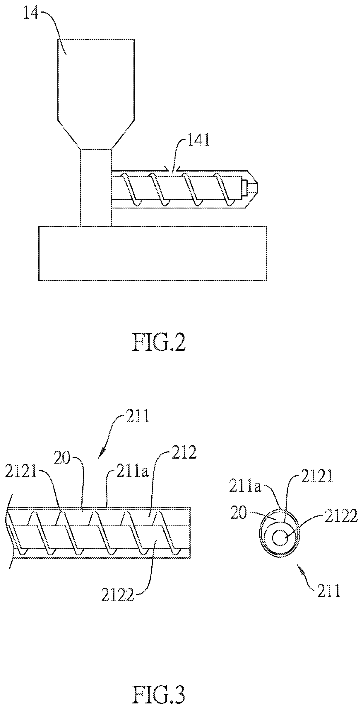
[0027]Referring to FIG. 1, the preparation system 1 includes a collection module 11, a selection module 12, a crushing module 13, and a plastic extrusion module 14. The collection module 11 guides waste plastic to the selection module 12 after collecting the waste plastic, wherein the selection module 12 separates out non-plastic substances from the waste plastic in a manual inspection manner, a magnet attraction manner or a mechanical inspection, and the waste plastic is crushed by a crushing module 13, then an output tube of the plastic extrusion module 14 heats and melts the waste plastic, and the plastic extrusion module 14 delivers the waste plastic which is melt to the decomposition system 2.

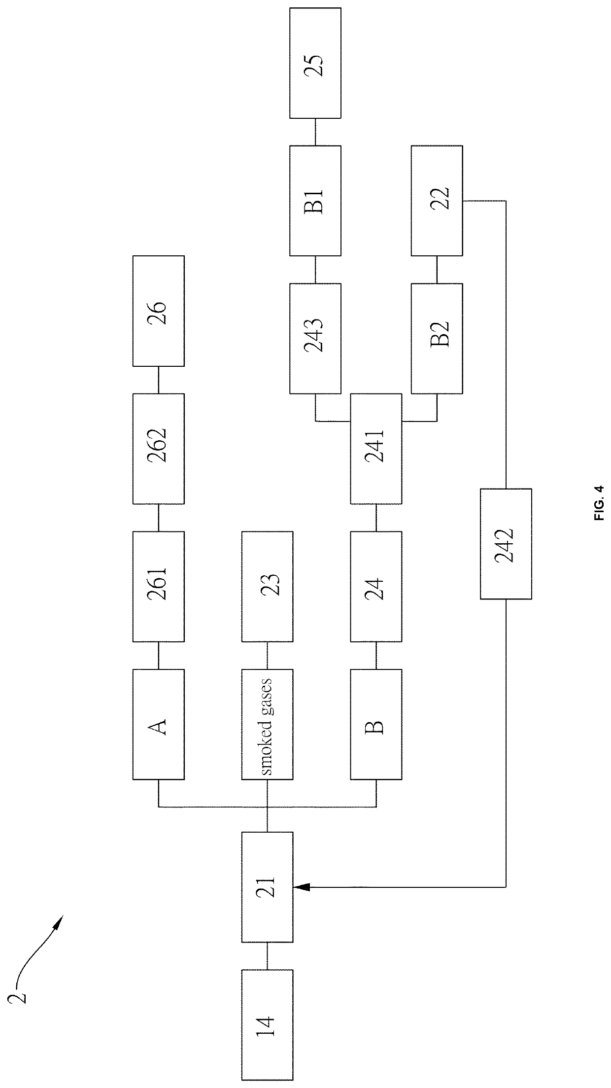
[0028]As shown in FIGS. 1 and 2, a secondary combustion cha...


PUM

PropertyMeasurementUnit
temperatureaaaaaaaaaa

Abstract

A multi-tube pyrolysis system for waste plastic contains: a preparation system, a decomposition system, and a filtration system. The preparation system includes a collection module, a selection module, a crushing module, and a plastic extrusion module. The decomposition system includes a reaction furnace, a primary combustion chamber assembly, a secondary combustion chamber assembly, a cooling module, an oil storage tank, and a carbon storage tank. The reaction furnace includes multiple first delivery tubes, and the carbon storage tank has a water filtering module. The filtration system includes a heat exchanger, a rapid cooling device, and a cyclone separation module.

Description

FIELD OF THE INVENTION[0001]The present invention relates to a multi-tube pyrolysis system for waste plastic which is capable of finishing pyrolysis process after feeding waste plastic successively.BACKGROUND OF THE INVENTION[0002]A conventional pyrolysis method for waste plastic has to feed waste plastic in batch, and the waste plastic is decomposed slowly. For example, it takes more than 10 hours to decompose the waste plastic.[0003]In addition, the decomposed oil is decomposed from the waste plastic in a small quantity and high labor cost. It is necessary to decompose the waste plastic by ways of additional energy.[0004]The present invention has arisen to mitigate and / or obviate the afore-described disadvantages.SUMMARY OF THE INVENTION[0005]The primary aspect of the present invention is to provide a multi-tube pyrolysis system for waste plastic which is capable of recycling waste plastic to serve as a fuel of heat source and acquiring recyclable resources (such as decomposed oil...

Claims


Application Information

Patent Timeline
Patent Type & Authority Patents(United States)
IPC IPC(8): C08J11/12C10B47/44C10B53/07B29B17/02B29B17/04C10B47/16B01J6/00B29B17/00
CPCC10B53/07B01J6/008C08J11/12C10B47/16C10B47/44B29B2017/001B29B2017/0203B29B2017/0296B29B2017/0496Y02P20/143Y02W30/62B29B17/02C10G1/10B29B17/04B29B2017/0272B29B2017/0244B29B2017/0021Y02W30/52
Inventor LEE, PENG-YANGHUANG, I-PIN
Owner LEE YUNG TENG
Why Eureka
Try Eureka