Method and apparatus for acoustically detecting fluid leaks

a technology of acoustic detection and fluid leakage, applied in lighting and heating apparatus, instruments, furnaces, etc., can solve the problems of affecting the detection effect, so as to achieve fast and reliable detection

Active Publication Date: 2022-02-22
TENOVA GOODFELLOW INC
View PDF20 Cites 0 Cited by
  • Summary
  • Abstract
  • Description
  • Claims
  • Application Information

AI Technical Summary

Benefits of technology

[0012]Another non-limiting object is to provide a leak detection device for a fuel or oil pipeline, duct or other fluid conduit, and which reduces the limitations and disadvantages of prior leak detection devices / solutions, and preferably those used in cooling circuits of industrial applications such as in panels, ducts, lances, tuyeres, metal casting moulds or the like and most preferably those used to respond to the problem of water leak detection in an EAF or other metallurgical furnaces where a serious explosion threat exists if liquid water comes in contact with molten metal.
[0016]The applicant has appreciated that providing an acoustic sensor assembly which operates to detect and / or sense transmitted known acoustic signals in a coolant-fluid flow of an installation cooling-fluid conduit, advantageously incident background noises which could lead to false readings may be reduced. In particular, the applicant has recognized that a coolant-fluid flow and in particular, a coolant-flow through cooling panels or channels such as those used in steel making applications advantageously may provide a more direct signal path to the steel making furnace or ancillary equipment. By detecting the known emitted audio signals transmitted through the coolant-fluid flows, it is possible to not only monitor the propagation path between the transmitted and the receiver and the ongoing operations of the furnace, but also detect furnace anomalies audibly, whilst achieving reduced interference from ambient noise signals. In one embodiment, the current invention provides an apparatus and method of leak detection based at least in part on the following principles:
[0021]More preferably, the invention provides a system and method of assessing fluid conduit and / or panel structure integrity by monitoring the acoustic response and / or variabilities of the fluid flow travelling inside the panel. Most preferably, the invention provides a system having at least one, and preferably two or more hydrophones or vibroacoustic sensors, which operate as audio transducer / receivers. The audio sensors are placed on, and more preferably within the conduit or pipe structure to be monitored, and preferably in contact with the travelling cooling fluid. To minimize background noise associated with fluid turbidity as the fluid flows through the conduit or pipe, the system most preferably operates so that the flow of fluid along the pipe is provided without an air space, and whereby the fluid is not provided as a free-surface or open channel flow. The applicant has appreciated that providing the fluid flow as a free-surfaceless pipe flow advantageously may minimize air entrainment and in-pipe turbidity which disadvantageously may result in the generation of undesirable secondary noise or acoustic signals.
[0023]In another embodiment, one or more acoustic transmitters or emitters are placed along, or more preferably directly within a fluid conduit or pipe, such as but not limited to the cooling fluid conduit of an industrial furnace cooling panel. The acoustic emitters are preferably omnidirectional transmitters, however linear and / or directional signal transmitters could also be used and operate to emit an output acoustic signal. One or more acoustic sensors are positioned along and preferably within the fluid conduit a distance from the signal transmitter to detect and sense the emitted acoustic signal. Most preferably at least an acoustic sensor is positioned at a downstream location spaced towards a mid-portion of the fluid flow stream, and separated a distance from the fluid conduit sidewall. Such positioning may advantageously reduce background noise issues associated with pipe and / or furnace cooling panel vibration.

Problems solved by technology

However, the introduction of water cooled panels has introduced the risk of water leaking into the furnace from damaged panels.
The coolant panels are subject to strong thermomechanical stress due to the extreme heat variations inside the furnace and the impact of scrap during the EAF charge phases.
Eventually, due to the expansion / contraction process, heat stress and scrap impact, the panel structure can crack leading to water spilling directly into the furnace.
An explosion risk exists whenever there is molten slag and metal in the furnace, however, this may become particularly acute if there is a sudden disturbance such as from unmelted scrap falling into the pool or when the EAF is rocked or tilted.
The development of such technology on a reliable level has proven difficult.
This practice relies only on the expertise of the EAF operator and may be susceptible to human error.
Experience has shown that a simple global in / out flow measurement is prone to high signal noise and poor response times. Regarding the pressure / flow monitoring of the water-cooling system, typically the furnace water panels are a sub-system of a more complex plant cooling scheme.
The resulting large scale sensor network increases system complexity which can affect reliability, maintenance and capital cost.
Heretofore, a major limitation of conventional off-gas analysis techniques used in the detection of water vapour remains developing software that can reliably differentiate actual water-leaks from such normal humidity variations generated by the process and typical furnace operations, while maintaining an acceptable false alarm rate for water leaks.
The vibrational noise produced by the leak is compared to the flow noise occurring in “normal conditions”, consequently generating an alarm when a significant difference is detected.
It has been appreciated that a main limitation of this approach consists in the significant vibrational noise of the EAF environment, which might mask the leak appearance.

Method used


Image

  • Method and apparatus for acoustically detecting fluid leaks
  • Method and apparatus for acoustically detecting fluid leaks
  • Method and apparatus for acoustically detecting fluid leaks

Examples


Embodiment Construction

[0075]The description below describes the methodology for the acoustic leak-detection system design in the preferred embodiment. It is understood that a similar methodology is applicable for design of acoustic leak-detection systems for other embodiments.

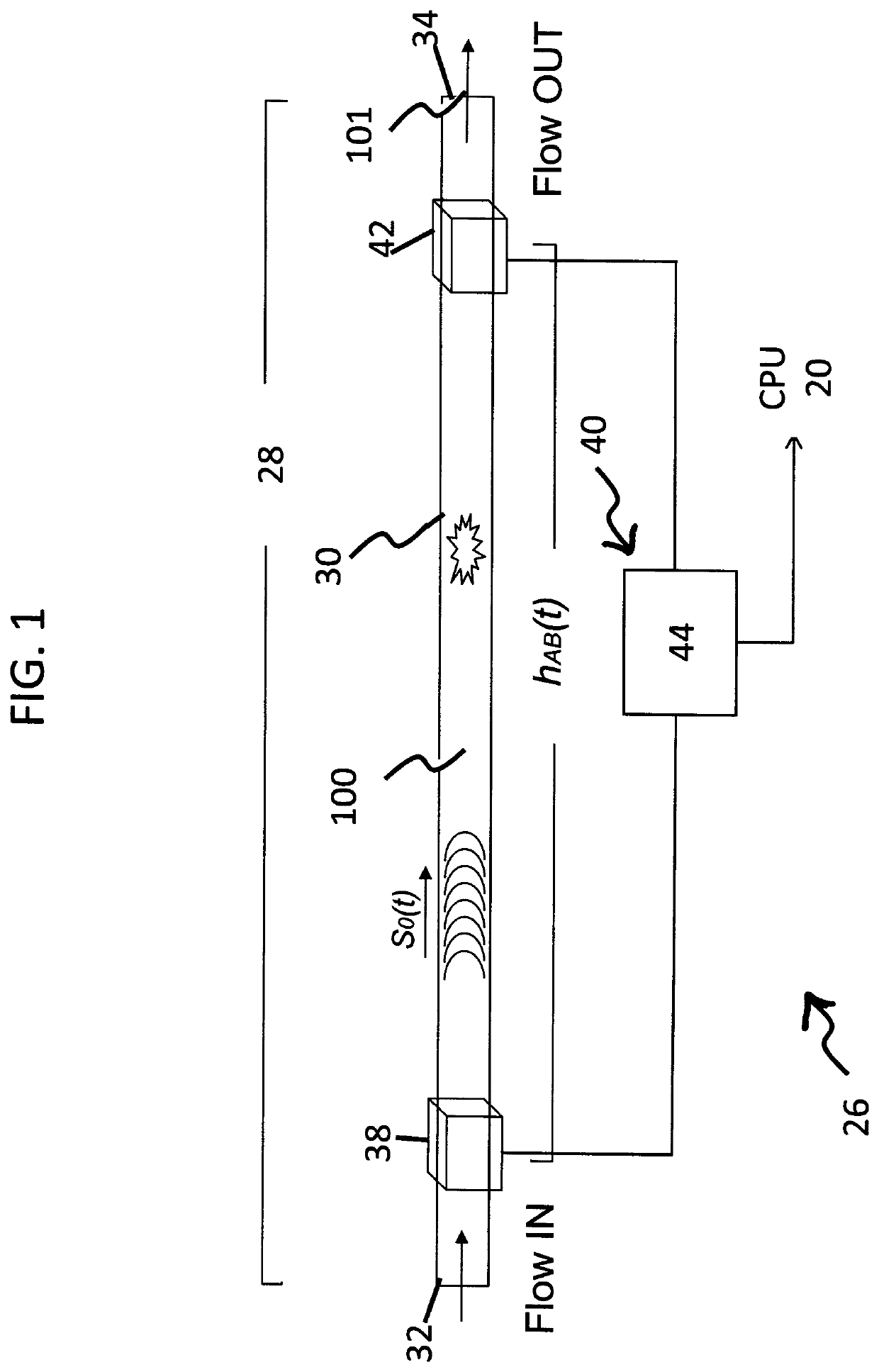
[0076]Reference may be had to FIG. 1, in which a leak detection system 26 is shown, as respectively including an acoustic signal emitter 38 and an acoustic signal receiver assembly 40 which includes at least one acoustic receiver or detector 42. The acoustic detector 42 and emitter 38 are preferably spaced along a conduit 28. Although not essential, the detection system 26 preferably includes a sensor system processor 44. In a non-limiting aspect the sensor processor 44 may be provided as part of the acoustic signal receiver assembly 40, and which preferably electronically communicates with and controls both the acoustic signal emitter 38 and the acoustic signal detector 42. More preferably, the sensor system processor 44 is further...


PUM

PropertyMeasurementUnit
frequencyaaaaaaaaaa
frequencyaaaaaaaaaa
frequencyaaaaaaaaaa

Abstract

A system used in monitoring one or more operating parameters of a coolant-fluid cooled industrial installation includes one or more an acoustic sensors positioned to receive and sense one or more acoustic signals in an installation coolant-fluid flow. The acoustic sensor assembly operates to emit and sense acoustic signals at frequency ranges above and / or below the background noise frequency ranges which are associated with the normal industrial installation operation. Output data signals representative of sensed acoustic signals are compared to target frequency profiles predetermined as representing an acoustic frequency associated with a predetermined installation operating parameter or event.

Description

RELATED APPLICATIONS[0001]This application claims priority and the benefit of 35 USC § 119(e) to U.S. Provisional Patent Application No. 62 / 481,753, filed 5 Apr. 2017, and which is incorporated herein by reference in its entirety.SCOPE OF THE INVENTION[0002]The present invention relates to a monitoring and detection system for monitoring the operating parameters of fluid contained and flowing in a pipe or channel. More preferably, the invention relates to a method and apparatus for detecting leaks in a pipeline of a fluid distribution systems in industrial applications, and more preferably an apparatus operable to provide the acoustic detection of fluid leaks in conduits, or pipes, such as water leaks which occur due to cooling panel fractures in steel making furnaces, such as Electric Arc Furnace (EAF).BACKGROUND OF THE INVENTION[0003]In the most preferred EAF steel making application, fluid or water cooled panels have been introduced to protect the upper-shell, roof and side-walls...

Claims


Application Information

Patent Timeline
Patent Type & Authority Patents(United States)
IPC IPC(8): G01M3/24G01M3/32G01N29/04G01M3/28
CPCG01M3/2807F23M5/08F22B37/38F27D1/12F27B3/085F27B3/24F27B3/28F27D2009/0032G01M3/243
Inventor LUCCINI, MARCOSCIPOLO, VITTORIO
Owner TENOVA GOODFELLOW INC
Why Eureka
Try Eureka