Driving circuit and method for stepping motor

a technology of driving circuit and stepping motor, which is applied in the direction of electronic commutation motor control, dynamo-electric converter control, control system, etc., can solve the problems of unfavorable and distortion of stepping motor, so as to reduce the heat generation of full bridge circuit and reduce the unsteady rotation of stepping motor

Active Publication Date: 2022-03-01
ROHM CO LTD
View PDF11 Cites 0 Cited by
  • Summary
  • Abstract
  • Description
  • Claims
  • Application Information

AI Technical Summary

Benefits of technology

[0017]According to the one embodiment, application of voltage across the coil with insertion of the inverse state every phase switching enables the gradient of the current varying to zero, to remain uniform. This arrangement enables reduction of distortion in the waveform of the coil current and inhibition of unsteady rotation of the stepping motor. In the inverse state, the current flows directly in the transistors instead of the body diodes thereof. Thus, loss can be reduced and heat generation of the full bridge circuit can be inhibited.
[0022]The driving circuit may be monolithically integrated on one semiconductor substrate. The “monolithic integration” includes a case where all constituent elements of the circuit are formed on the semiconductor substrate and a case where main constituent elements of the circuit are monolithically integrated. For example, for adjustment of circuit constants, part of resistors and capacitors may be provided outside the semiconductor substrate. Integration of the circuit on one chip enables reduction in circuit area and enables circuit elements to remain uniform in characteristic.

Problems solved by technology

As a result, the waveform of the coil current IOUT1 is asymmetric, so that distortion occurs.
The distortion causes unsteady rotation of the stepping motor.
At excitation positions #2 and #5, regenerative current flows in each body diode, so that useless heat generation occurs in the full bridge circuit.

Method used


Image

  • Driving circuit and method for stepping motor
  • Driving circuit and method for stepping motor
  • Driving circuit and method for stepping motor

Examples


modification 1

[0102]In the driving circuit 200 of FIG. 9, transition is made from the inverse state to the off state in accordance with the zero-current detection signal SZC, but this is not limitative. For example, with the voltage across the coil being monitored, the coil current IOUT1 having decreased close to zero may be detected on the basis of a result of the monitoring. Alternatively, transition may be made to the off state after predetermined time passes after transition to the inverse state.

modification 2

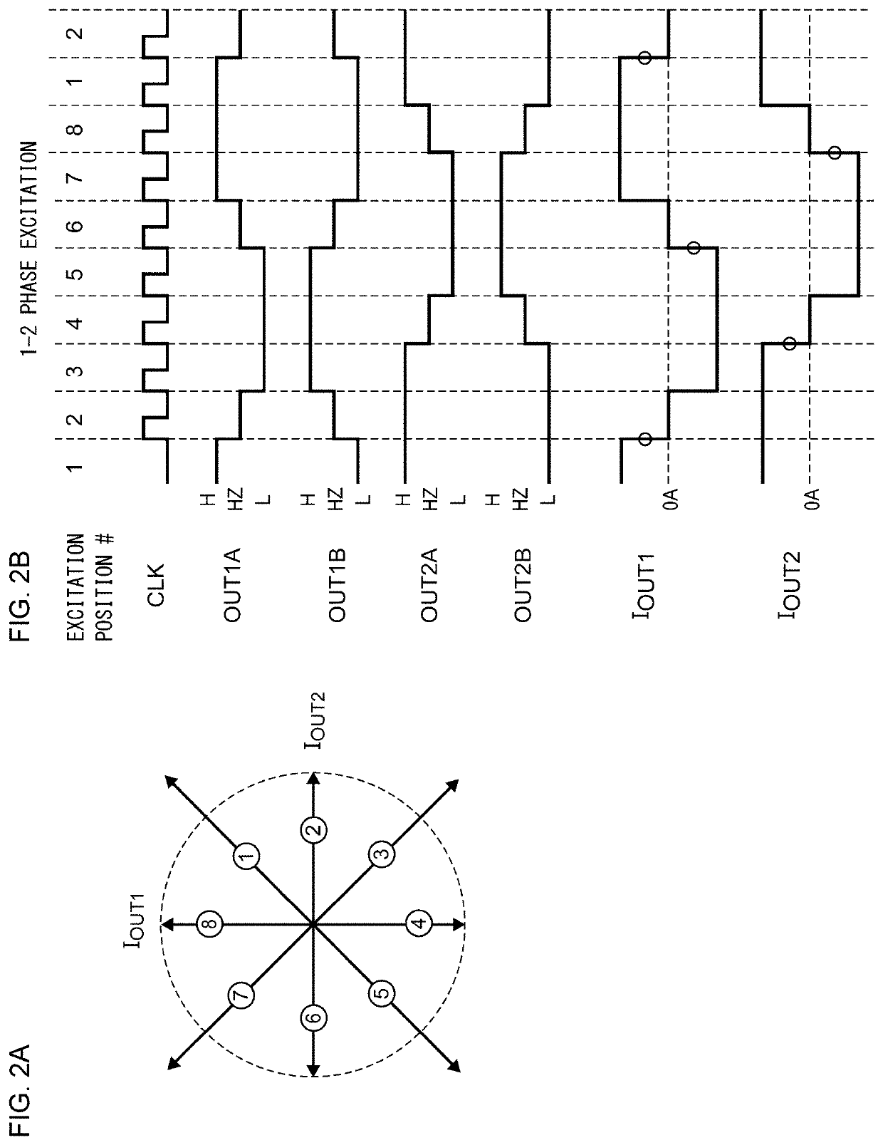
[0103]In the embodiment, the case where the excitation position changes clockwise has been described. A similar manner is made at the time of counterclockwise rotation. A case where counterclockwise rotation is made in the 1-2 phase excitation will be described with reference to FIG. 2A. Regarding the current IOUT1 (full bridge circuit 202_1), the transition from excitation position #7 to excitation position #6 and the transition from excitation position #3 to excitation position #2 involve the phase changing. Therefore, with the timing chart of FIG. 2B inverted left and right, the inverse state needs inserting in the fronts of excitation positions #6 and #2. Similarly, regarding the current IOUT2 (full bridge circuit 202_2), the transition from excitation position #1 to excitation position #8 and the transition from excitation position #5 to excitation position #4 involve the phase changing. With the timing chart of FIG. 2B inverted left and right, the inverse state needs inserting...

modification 3

[0104]In the embodiment, the case of the 1-2 phase excitation has been described. However, the excitation method is not limited to the 1-2 phase excitation. FIGS. 13A and 13B explanatorily illustrate quarter-step drive. FIG. 13A explanatorily illustrates the excitation position of the quarter-step drive. In the quarter-step drive, an electrical angle of 360° is divided into 16 segments. Therefore, 16 excitation positions are present.

[0105]FIG. 13B is a waveform chart of the operation of the driving circuit 200 in the quarter-step drive. Focus on the coil current IOUT1, the transition from excitation position #2 to excitation position #3 and the transition from excitation position #10 to excitation position #11 involve the phase switching. Therefore, the inverse state is inserted in the fronts of excitation positions #3 and #11. Similarly, focus on the coil current IOUT2, the transition from excitation position #6 to excitation position #7 and the transition from excitation position ...


PUM


Abstract

Excitation position is changed in accordance with an external clock. The state of a full bridge circuit including four transistors connected to a coil of a stepping motor, is controlled in accordance with the excitation position. At the time of transition from the excitation position at which coil current that flows in the coil is nonzero to the excitation position at which the coil current is zero, a switch is made to (i) the inverse state where the on or off state of each of the four transistors before the transition is inverted, and then a switch is made to (ii) the off state where all the four transistors are off.

Description

CROSS REFERENCE FOR RELATED APPLICATIONS[0001]The present invention claims priority under 35 U.S.C. § 119 to Japanese Application No. 2019-045874 filed Mar. 13, 2020, the entire content of which is incorporated herein by reference.BACKGROUND OF THE INVENTION1. Field of the Invention[0002]The present invention relates to driving technology for a stepping motor.2. Description of the Related Art[0003]Stepping motors have been widely adopted in electronic equipment, industrial machinery, and robots. Such a stepping motor is a synchronous motor that rotates in synchronization with an input clock generated by a host controller, and has excellent controllability in starting, stopping, and positioning. Furthermore, the stepping motor enables open-loop positional control, and is characteristically suitable for digital signal processing.[0004]FIG. 1 is a block diagram of a motor system including a conventional stepping motor and a driving circuit therefor. A host controller 2 supplies an inpu...

Claims


Application Information

Patent Timeline
Patent Type & Authority Patents(United States)
IPC IPC(8): H02P8/00H02P8/12H02P8/34
CPCH02P8/12H02P8/34H02P8/16H02P6/182
Inventor HASHIMOTO, HIROKI
Owner ROHM CO LTD
Why Eureka
Try Eureka