Low temperature melting and mid temperature melting lead-free solder paste with mixed solder alloy powders

a technology of alloy powders and low temperature melting, which is applied in the direction of welding/cutting media/materials, manufacturing tools, and soldering apparatus, etc., can solve the problems that the melting temperature of eutectic bi—sn and near-eutectic bi—sn modified alloys are brittle in nature, and the melting temperature of these two alloys may be too low to allow both alloy systems, so as to achieve significant changes in composition and increase sn conten

Active Publication Date: 2022-03-08
INDIUM CORP
View PDF51 Cites 3 Cited by
  • Summary
  • Abstract
  • Description
  • Claims
  • Application Information

AI Technical Summary

Benefits of technology

[0006]The lead-free mixed solder powder paste described herein may address the need for reliable low melting temperature and middle melting temperature solders, including ones that are strong and ductile. For example, lower melting temperature solders of eutectic Sn—In and modifications thereof, Bi—Sn and modifications thereof, Sn—In—Ag, and Bi—Sn—Ag may be mixed with Sn-rich (e.g., SnAg, SnCu, SnAgCu, SnSb, etc.) solder alloys and modifications thereof to form the solder paste. During reflow, the lower melting temperature solder alloy melts first, and may spread onto the surface to wet and react with surface metallization to form interface IMCs. The higher melting temperature solder alloy (e.g., SnAg, SnCu, SnAgCu, SnSb, SnAgSb, SnAgCuSb, SnAgCuBi, SnAgCuBiSb, etc.) may continuously dissolve into the molten solder since both the lower melting temperature and higher melting temperature solder alloys are composed of significant amounts of Sn.
[0007]The continuous dissolution of Sn from an Sn-rich solder into a molten solder may change the composition significantly. As a result, the liquidus temperature may increase with increasing Sn content for both Sn—In and Bi—Sn solder systems. With enough Sn dissolution during reflow, the composition may move into the Sn-rich solid solution zone from the eutectic zone. Afterwards, the remelting temperature of the joint matrix may bear with the solidus temperature of the solid solution, which increases with increasing Sn-content.
[0008]The remaining higher melting temperature solder powder may be trapped in the solid solution matrix if it is not completely dissolved during reflow. The trapped remaining higher melting temperature solder powder may remain as colonies embedded in the matrix. The existence of these colonies may enhance the mechanical performance of the matrix. Depending on the alloys being selected, the reflow joint may exhibit the combination of merits from both constituent powders.
[0009]In contrast to TLPB technology, implementations described herein do not need to rely on IMC formation to increase the melting temperature at all. It is not expected that interfacial IMC phases will form on the surface of the higher melting temperature solder alloys. Rather, the solder paste may be reflowed at a relatively lower peak temperature, while the higher melting temperature solder alloy powders are continuously dissolved into the molten lower melting temperature solder alloy to form a homogeneous liquid solution. The dissolution of the higher melting temperature solder powder into the molten lower melting temperature one may continue during the whole reflow process. In design, the ratio of the constituent powders and the powder sizes may be controlled to allow the existence of the remaining high melting phase colonies after reflow and solidification, which would improve mechanical performance improvement.

Problems solved by technology

Eutectic Bi—Sn and near-eutectic Bi—Sn modified alloys are brittle in nature because of the existence of a high Bi content.
In addition, the melting temperature of these two alloys may be too low to allow both alloy systems to survive the board-level reliability requirement of 125° C.

Method used


Image

  • Low temperature melting and mid temperature melting lead-free solder paste with mixed solder alloy powders
  • Low temperature melting and mid temperature melting lead-free solder paste with mixed solder alloy powders
  • Low temperature melting and mid temperature melting lead-free solder paste with mixed solder alloy powders

Examples


Embodiment Construction

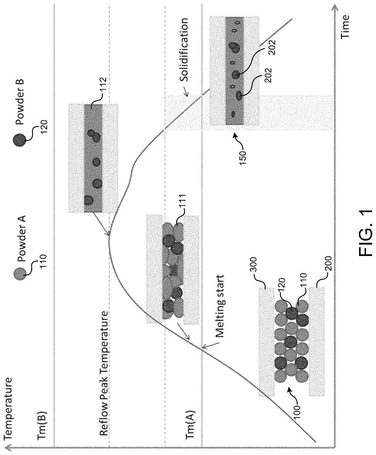
[0005]Implementations of the disclosure are directed to a lead-free mixed solder powder paste suitable for low temperature to middle temperature soldering applications. The solder paste may include at least two solder powder alloys having significantly different solidus temperatures. The solder paste may be designed for reflow at a peak temperature below the solidus temperature of solder powder having the higher solidus temperature but above the melting temperature of the lower one.

[0006]The lead-free mixed solder powder paste described herein may address the need for reliable low melting temperature and middle melting temperature solders, including ones that are strong and ductile. For example, lower melting temperature solders of eutectic Sn—In and modifications thereof, Bi—Sn and modifications thereof, Sn—In—Ag, and Bi—Sn—Ag may be mixed with Sn-rich (e.g., SnAg, SnCu, SnAgCu, SnSb, etc.) solder alloys and modifications thereof to form the solder paste. During reflow, the lower m...


PUM

PropertyMeasurementUnit
melting temperatureaaaaaaaaaa
solidus temperatureaaaaaaaaaa

Abstract

Implementations of the disclosure are directed to a lead-free mixed solder powder paste suitable for low temperature to middle temperature soldering applications. The lead-free solder paste may consist of: an amount of a first solder alloy powder between 44 wt % and 83 wt %, the first solder alloy powder comprising Sn; an amount of a second solder alloy powder between 5 wt % to 44 wt %, the second alloy powder comprising Sn, where the first solder alloy powder has a liquidus temperature lower than a solidus temperature of the second solder alloy powder; and a remainder of flux. The solder paste may be used for reflow at a peak temperature below the solidus temperature of the higher solidus temperature solder powder but above the melting temperature of the lower solidus temperature one.

Description

CROSS-REFERENCE TO RELATED APPLICATIONS[0001]This application claims priority to Chinese Patent Application No. 2019103830543 filed on May 9, 2019, and titled “Mid-melting and low-melting lead-free solder paste produced by mixing solder powders.”DESCRIPTION OF THE RELATED ART[0002]The electronics industry is moving toward miniaturized components with an increasing number of integrated system-in-package (SIP) designs. In some SIP designs, step soldering involving multiple reflows may be desired to interconnect the components together into one assembly. To reduce the risk of solder remelting during a subsequent reflow (e.g., after the first reflow), solders of different melting temperature may be required. SnAgCu solders having a melting temperature around 217° C. are commonly used for a first stage soldering interconnection. For a second stage soldering interconnection, the melting temperature of the solder may need to be significantly lower than that of the SnAgCu solder. Commonly, ...

Claims


Application Information

Patent Timeline
Patent Type & Authority Patents(United States)
IPC IPC(8): B23K35/00B23K1/00B23K35/26C22C13/02B23K35/02B23K1/008
CPCB23K35/262B23K1/008B23K35/025C22C13/02B23K1/00B23K35/264H05K3/3485H05K3/3463H05K2201/0272B23K1/0016B23K1/203B23K2101/36
Inventor ZHANG, HONGWENCHEN, FENMUTUKU, FRANCISGENG, JIELEE, NING-CHENG
Owner INDIUM CORP
Why Eureka
Try Eureka