Eureka AIR delivers breakthrough ideas for toughest innovation challenges, trusted by R&D personnel around the world.

Electromagnetic braking system and control method for rapid compression machine

a technology of electric braking and rapid compression machine, which is applied in the direction of braking system, mechanical apparatus, instruments, etc., can solve the problems of affecting the mechanical structure and personal safety, the deformation of the braking system, and the unaddressed need in the art, so as to reduce the rebound phenomenon of the piston, reduce the noise of the brake, and improve the accuracy and reliability

Active Publication Date: 2022-03-15
TIANJIN UNIV
View PDF11 Cites 0 Cited by
  • Summary
  • Abstract
  • Description
  • Claims
  • Application Information

AI Technical Summary

Benefits of technology

[0012]step 4, decelerating the push rod forwardly, when the second position signal is detected, that is when the second shading plate blocks the photoelectric sensor, the piston of the rapid compressor still has a small speed and has a small distance Δl from the top dead center; at this time, switching the transfer switches to the same port by the CCU, so that the currents of the two electromagnetic coils are in the same direction, and the currents generate mutual attraction electromagnetic forces; changing current magnitude so that the piston of the rapid compressor fully reaches the top dead center under the action of the air pressure of the driving cylinder and electromagnetic force, thus further tightening the electromagnetic braking piston and the electromagnetic brake ring, thereby preventing the piston from rebounding; further, balancing the in-cylinder pressure generated during the combustion by the air pressure of the driving cylinder and the electromagnetic force.
[0014]Compared to the prior art, the present invention combines the electromagnetic principle and the working characteristics of the rapid compressor, and uses the advanced control unit and the control method, has the advantages of significantly reducing rebound phenomenon of the piston, reducing the brake noise, so that obtained experimental data is more accurate and reliable, and thus closer to the actual operating conditions of the internal combustion engine. Meanwhile, the present invention captures the position signal and the speed signal through the sensor and feeds back the current signal, thereby generating an electromagnetic force fitting the magnitude and the speed, and more accurately stopping the piston at the preset position, thereby achieving a better control effect.

Problems solved by technology

However, there are some defects in these two methods.
For example, the hydraulic braking method is highly dependent on the working conditions, which commonly causes the piston rebound so as to change the thermodynamic state in the cylinder, affecting the ignition delay time and combustion phase; whereas the mechanical braking method works better than the hydraulic braking method, but there are mechanical wear and impact problems that affect the mechanical structure and personal safety.
Therefore, a heretofore unaddressed need exists in the art to address the aforementioned deficiencies and inadequacies.

Method used


Image

  • Electromagnetic braking system and control method for rapid compression machine
  • Electromagnetic braking system and control method for rapid compression machine
  • Electromagnetic braking system and control method for rapid compression machine

Examples


Embodiment Construction

[0024]The present invention will be described in detail below with reference to the drawings in conjunction with the embodiments. The invention is not limited to the specific embodiment, and the description is not intended to limit the thereto.

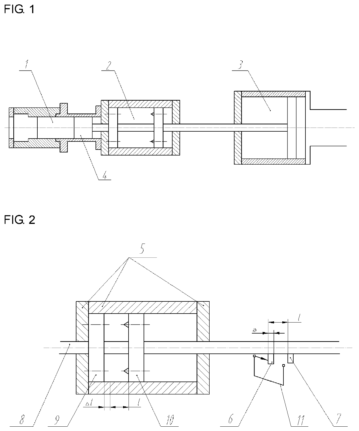
[0025]FIG. 1 shows a schematic diagram of an electromagnetic braking rapid compressor according to the present invention, including a combustion chamber 1, an electromagnetic braking system 2, a driving device 3 and a piston 4.

[0026]FIG. 2 shows a schematic diagram of the electromagnetic braking system. The electromagnetic braking system includes an electromagnetic shielding braking cylinder 5 made of magnetic isolating material, a push rod 8 passing through the electromagnetic shielding braking cylinder 5, an electromagnetic braking ring 9 fixed to the electromagnetic shielding braking cylinder 5, an electromagnetic braking piston 10 fixed to the push rod 8, two shading plates 6 and 7 and a photoelectric sensor 11 fixed near the push rod. The...


PUM


Abstract

An electromagnetic braking system and control method, with the system having a CCU, a braking cylinder, a push rod, an electromagnetic braking ring, an electromagnetic braking piston fixed to the push rod, a first shading plate and a second shading plate, a photoelectric sensor fixed near the push rod, and an electromagnetic braking control circuit, and the control method including following the steps: initial estimating of the braking distance (l) according to the current magnitude, electromagnetic force between the two electromagnetic coils and initial velocity (v) of the push rod, arranging a restoration distance (Δl) between the top dead center and the piston after braking, installing two shading plates and the photoelectric sensor; and setting the distance between the two electromagnetic coils to when the starts braking.

Description

FIELD OF THE INVENTION[0001]The invention relates to an electromagnetic braking system and control method for a rapid compressor, involves in the technical field of thermal energy and power engineering testing, and in particular relates to a system and control method of rapid compressor for combustion engine simulation and fuel chemical kinetics research.BACKGROUND OF THE INVENTION[0002]The rapid compressor provides a fundamental experimental platform to simulate the combustion engine working process and fuel combustion. The process of the rapid compressor simulates a single compression stroke of the combustion engine is as follows: pushing the compression piston by external force, instantaneously compressing the premixed gas in the combustion chamber to reach a high temperature and high pressure thermodynamic state, and then stopping the compression piston by the braking system to maintain the premixed gas in the combustion cylinder in a high temperature and high pressure thermodyn...

Claims


Application Information

Patent Timeline
Patent Type & Authority Patents(United States)
IPC IPC(8): F16D63/00F16D66/00F16D121/04F16D121/20
CPCF16D63/002F16D2066/003F16D2121/04F16D2121/20G01M15/00G01M15/02B60T13/748
Inventor PAN, JIAYINGWANG, LEIWEI, HAIQIAOSHU, GEQUNLIU, CHANGWENMA, GUOBIN
Owner TIANJIN UNIV
Why Eureka
Eureka Blog
Learn More