
Probing a structure of concrete by means of electromagnetic waves

a technology of electromagnetic waves and concrete, applied in the field of probing the structure of concrete, can solve the problems of high power consumption and complex analysis types, and achieve the effect of low power consumption

Active Publication Date: 2022-03-15
PROCEQ SA
View PDF26 Cites 1 Cited by
  • Summary
  • Abstract
  • Description
  • Claims
  • Application Information

AI Technical Summary

Benefits of technology

The invention includes a method and device for measuring pulses using a series of probe signals with different frequencies. This technique reduces power consumption because the signals are analyzed in the frequency domain, which allows for lower sampling rates. The demodulated signal is also more robust against drift and noise. Additionally, the invention allows for varying the amplitudes of individual probe signals based on their frequency, which can help reduce sensitivity to spectral noise at certain frequencies. Overall, this invention offers reduced power consumption and improved accuracy in measuring pulses.

Problems solved by technology

This type of analysis requires complex hardware that is able to sample the returning echoes with high temporal resolution.
This type of hardware needs to perform a high-frequency sampling of the echo and therefore has high power consumption.
Also, signals over a wide frequency range have to be processed, which makes the technology sensitive to interference with radio communication signals, such as WiFi signals.

Method used


Image

  • Probing a structure of concrete by means of electromagnetic waves

Examples


Embodiment Construction

[0047]Overview:

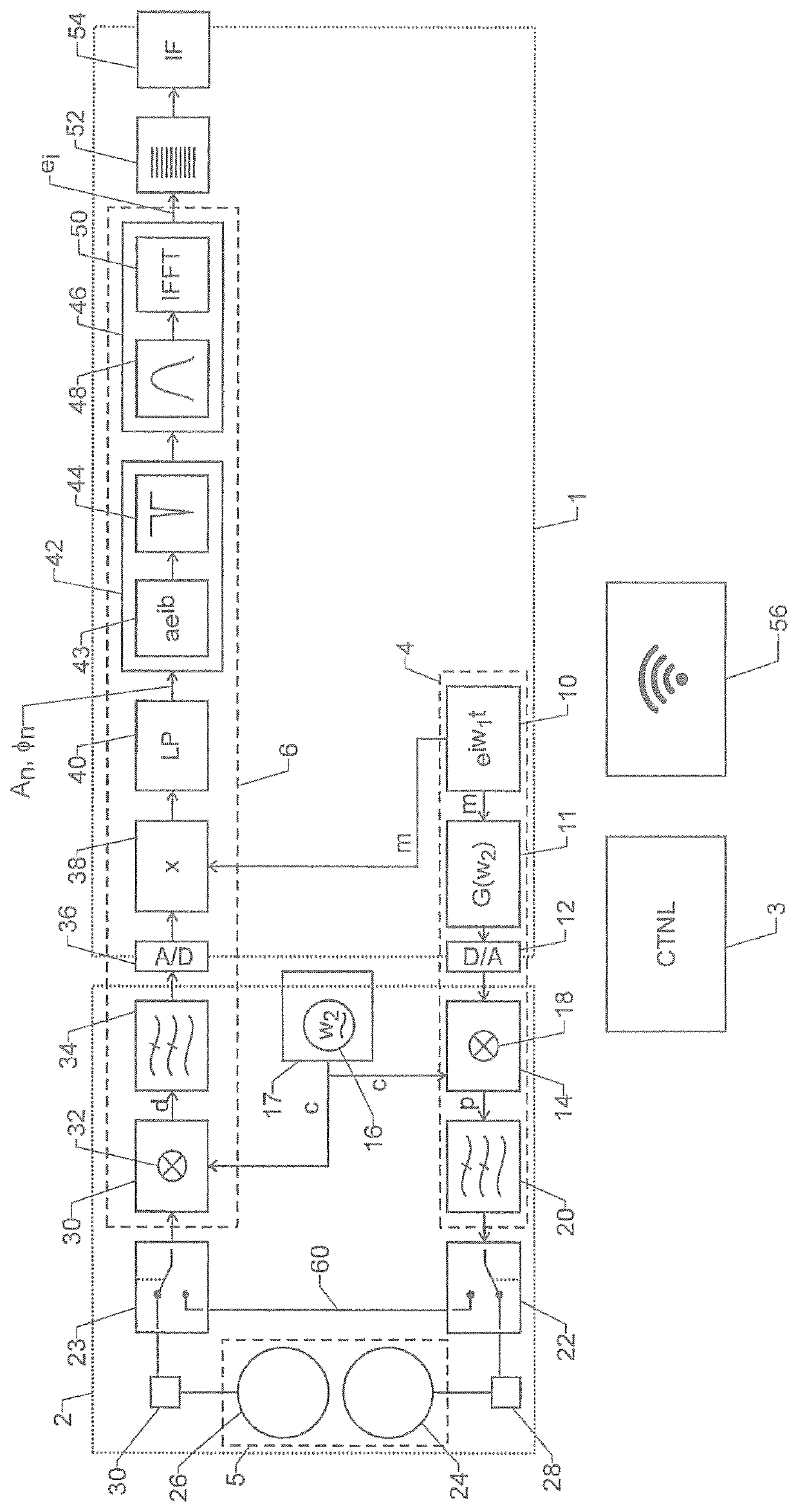
[0048]The device of FIG. 1 comprises a first section 1 of digital processing circuitry and a second section 2 of analogue processing circuitry.

[0049]First section 1 is advantageously formed by an FPGA circuit or some other circuit technology allowing to implement sequential logic.

[0050]The device further comprises a control unit 3, which may be implemented, at least partially, as part of first section 1 and / or as a separate, digital device, such as a microprocessor.

[0051]The most important parts of the device described here are:[0052]A probe signal generator 4 adapted and structured to generate an electromagnetic wave to be sent into the structure to be probed.[0053]An antenna 5 for coupling the electromagnetic wave into the structure and for receiving an echo therefrom.[0054]An echo signal receiver 6 adapted and structured to process the echo.

[0055]The function and design of these parts are described in more detail in the following sections.

[0056]Probe Signal Generat...


PUM

PropertyMeasurementUnit
frequencyaaaaaaaaaa
frequencyaaaaaaaaaa
frequencyaaaaaaaaaa

Abstract

In order to accurately probe a structure of concrete, a series of probe signals with defined carrier frequencies are generated by a probe signal generator and coupled into the structure by an antenna. The returning echo signals are processed by an echo signal receiver. Processing includes phase and amplitude detection in a multiplier, frequency-specific scaling in a scaling unit, replacement of the measured phases and amplitudes in an interpolation unit, and the generation of time-domain data in a Fourier transformation module. The device is robust against RF noise, accurate and low-power.

Description

TECHNICAL FIELD[0001]The invention relates to a method for probing a structure of concrete where an electromagnetic wave is sent into the structure, an echo of the wave is received from the structure, and internal features of the structure are derived from the echo.[0002]The invention also relates to a device for carrying out said method.BACKGROUND ART[0003]It has been known to probe the structure of concrete by means of electromagnetic waves. For doing so, a short electromagnetic pulse is sent into the structure and its echo is received. The structure can then be derived from the amplitude and delay of the peaks in the echo.[0004]This type of analysis requires complex hardware that is able to sample the returning echoes with high temporal resolution. This type of hardware needs to perform a high-frequency sampling of the echo and therefore has high power consumption. Also, signals over a wide frequency range have to be processed, which makes the technology sensitive to interference...

Claims


Application Information

Patent Timeline
Patent Type & Authority Patents(United States)
IPC IPC(8): G01N33/38G01N22/02
CPCG01N33/383G01N22/02G01S13/88G01S13/38G01S7/4069G01M7/025G01N27/00G01N33/38
Inventor LEHNER, SAMUELMENNICKE, RALPH
Owner PROCEQ SA
Learn More