
Radiotherapy planning with improve accuracy

a radiation therapy and accuracy technology, applied in radiation therapy, medical science, radiation therapy, etc., can solve the problems of generating estimated electron density maps from magnetic resonance (mr) images, and obtaining maps from mr images, e.g., lookup operations, etc., to improve the control of radiation dose distribution.

Active Publication Date: 2022-03-29
KONINKLJIJKE PHILIPS NV
View PDF12 Cites 13 Cited by
  • Summary
  • Abstract
  • Description
  • Claims
  • Application Information

AI Technical Summary

Benefits of technology

The present patent describes a method for planning radiotherapy treatment using a magnetic resonance imaging (MRI) image of a patient's body. The method allows for better control of the radiation dose distribution and provides better accuracy in estimating the amount of radiation that will be absorbed by the patient's body. The method also saves resources and processing time by avoiding the need for a computed tomography (CT) image. The method can adapt non-perfect MRIs to improve their accuracy for therapy planning and can assess the impact of certain changes to the MRIs. The method is reliable and can be used without the need for a CT image. The patent includes a technical means for selecting and modifying certain voxels in the MRI image to improve the accuracy of the radiation dose distribution.

Problems solved by technology

Creating estimated electron density maps from magnetic resonance (MR) images is a problem that occurs, e.g., with integrated positron emission tomography (PET) / MR systems, where an attenuation map needs to be estimated for the attenuation correction of the PET images, or with radiation therapy planning based on MR, where electron density maps are required for the treatment simulation.
Hence those maps when derived from the MR image by, e.g., a lookup operation, as is commonly done when estimating these maps from computed tomography (CT) images, may not be accurate.

Method used


Image

  • Radiotherapy planning with improve accuracy
  • Radiotherapy planning with improve accuracy
  • Radiotherapy planning with improve accuracy

Examples


Embodiment Construction

[0042]In the following, like numbered elements in the figures are either similar elements or perform an equivalent function. Elements which have been discussed previously will not necessarily be discussed in later figures if the function is equivalent.

[0043]Various structures, systems and devices are schematically depicted in the figures for purposes of explanation only and so as to not obscure the present invention with details that are well known to those skilled in the art. Nevertheless, the attached figures are included to describe and explain illustrative examples of the disclosed subject matter.

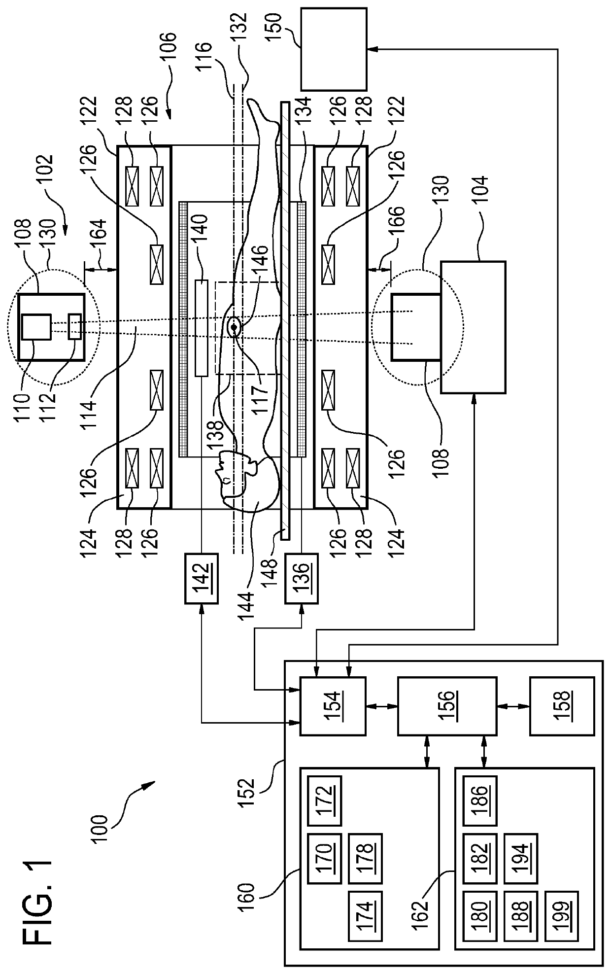
[0044]FIG. 1 shows a cross-sectional and functional view of a therapy system 100. The therapy system 100 is shown as comprising a radiotherapy apparatus 102 and a magnetic resonance imaging module 106. The radiotherapy apparatus 102 comprises a ring mechanism 108. The ring mechanism 108 supports a radiotherapy source 110. The radiotherapy source 110 is representative and may be a LINAC ...


PUM


Abstract

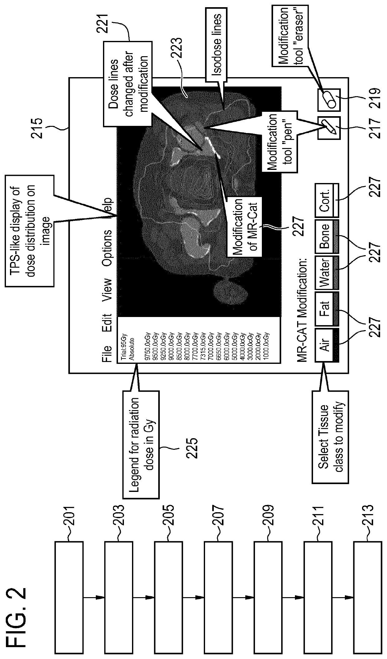
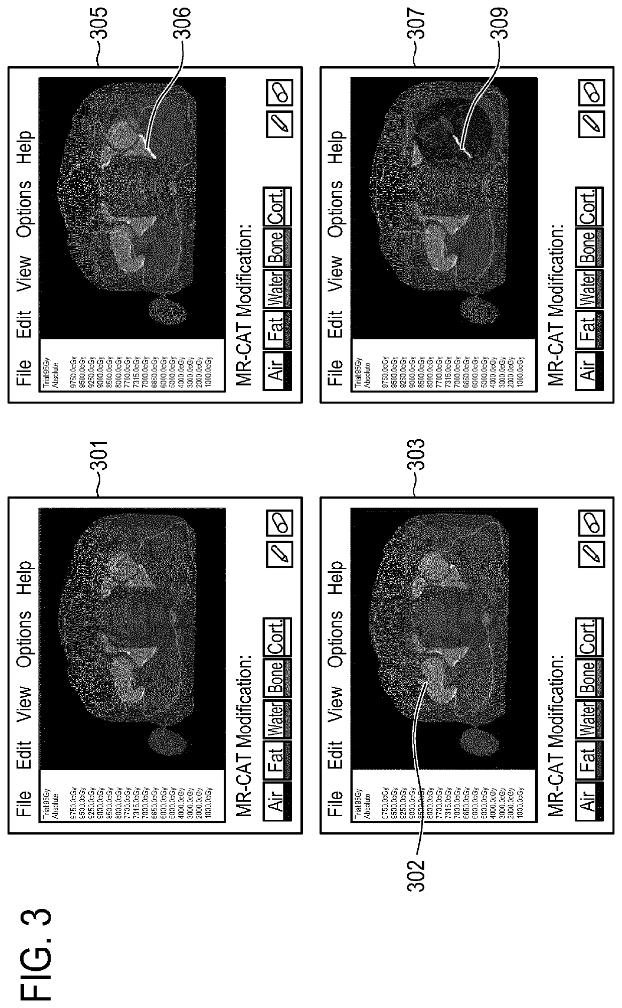
The present disclosure relates to a method for controlling a magnetic resonance imaging guided radiation therapy apparatus comprising a magnetic resonance imaging system. The method comprises: acquiring magnetic resonance data using the magnetic resonance imaging system and the pulse sequence from an imaging volume; segmenting the magnetic resonance data into a plurality of segments indicating respective tissues in the imaging volume; creating a bulk electron density map of the imaging volume from the plurality of segments; displaying the bulk electron density map and radiation dose distributions for the plurality of segments on a graphical user interface, wherein the radiation dose distributions are determined using the bulk electron density map; receiving a modification signal for modifying at least a first segment of the segments; recreating the bulk electron density map using the modified first segment, and recalculating the radiation dose distribution using the bulk electron density map; redisplaying the bulk electron density map and the radiation dose distributions on the graphical user interface.

Description

CROSS REFERENCE TO RELATED APPLICATIONS[0001]This application is a U.S. national phase application of International Application No. PCT / EP2016 / 057953, filed on Apr. 12, 2016, which claims the benefit of EP Application Serial No. 15163484.7 filed on Apr. 14, 2015 and is incorporated herein by reference.TECHNICAL FIELD OF THE INVENTION[0002]The invention relates to energy treating devices, in particular to the use of a therapy system for radiotherapy planning with improved accuracy.BACKGROUND OF THE INVENTION[0003]Creating estimated electron density maps from magnetic resonance (MR) images is a problem that occurs, e.g., with integrated positron emission tomography (PET) / MR systems, where an attenuation map needs to be estimated for the attenuation correction of the PET images, or with radiation therapy planning based on MR, where electron density maps are required for the treatment simulation. However, due to the physics of the image acquisition, MR intensities do not uniquely corres...

Claims


Application Information

Patent Timeline
Patent Type & Authority Patents(United States)
IPC IPC(8): A61N5/10A61B5/055
CPCA61N5/1039A61B5/055A61N2005/1074
Inventor SCHADEWALDT, NICOLERENISCH, STEFFENPREVRHAL, SVENSCHULZ, HEINRICHBLAFFERT, THOMAS
Owner KONINKLJIJKE PHILIPS NV
Learn More