Multi-channel folded optical system

a multi-channel, optical system technology, applied in the field of telescope refractive lenses, can solve the problems of chromatic aberration, difficult task of creating an image cube from multiple images, etc., and achieve the effect of reducing vibration and reducing image registration problems

Active Publication Date: 2022-03-29
CHARLES STARK DRAPER LABORATORY
View PDF12 Cites 0 Cited by
  • Summary
  • Abstract
  • Description
  • Claims
  • Application Information

AI Technical Summary

Benefits of technology

[0007]One way to simplify or eliminate image registration issues is to acquire images in the different spectral bands with a common boresight. This approach also renders the system more robust against vibration since the vibration affects the different images similarly. The word “image” is used to describe where a detector (image sensor or focal plane array, spectrometer, diode, etc.) or emitter (LED, laser, etc.) may be used in place.
[0008]The invention concerns optical systems, such as optical imaging and / or projection systems, with potentially improved thermal characteristics (athermal, temperature insensitive) and potentially improved pressure insensitivity. The systems might use diamond-turned and / or molded (plastic) concave and convex mirrors as part of the imaging and / or projection system to minimize unwanted dispersion and enable athermalization.
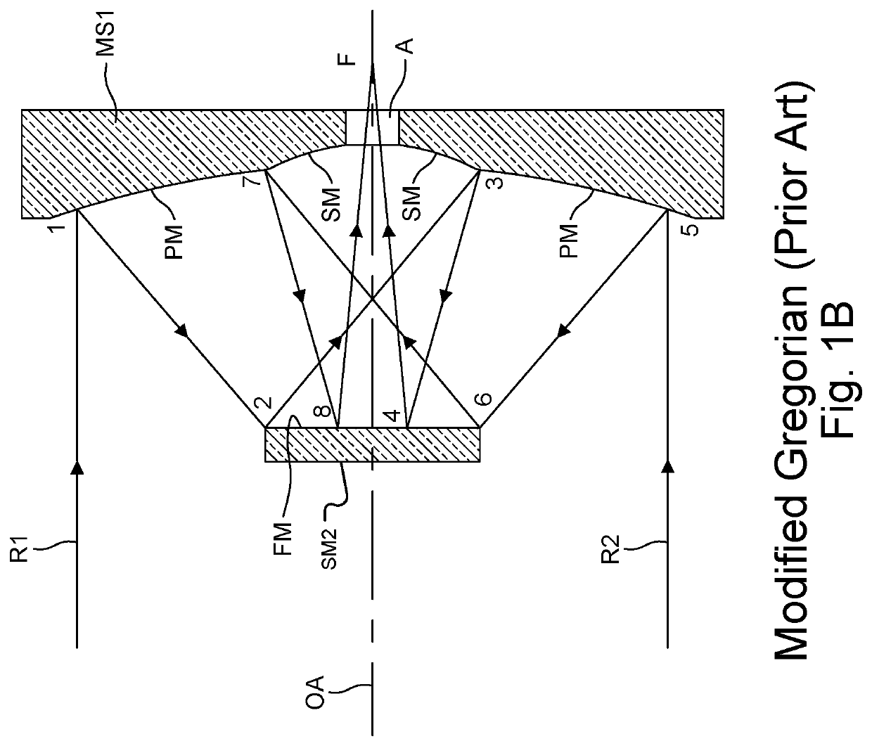
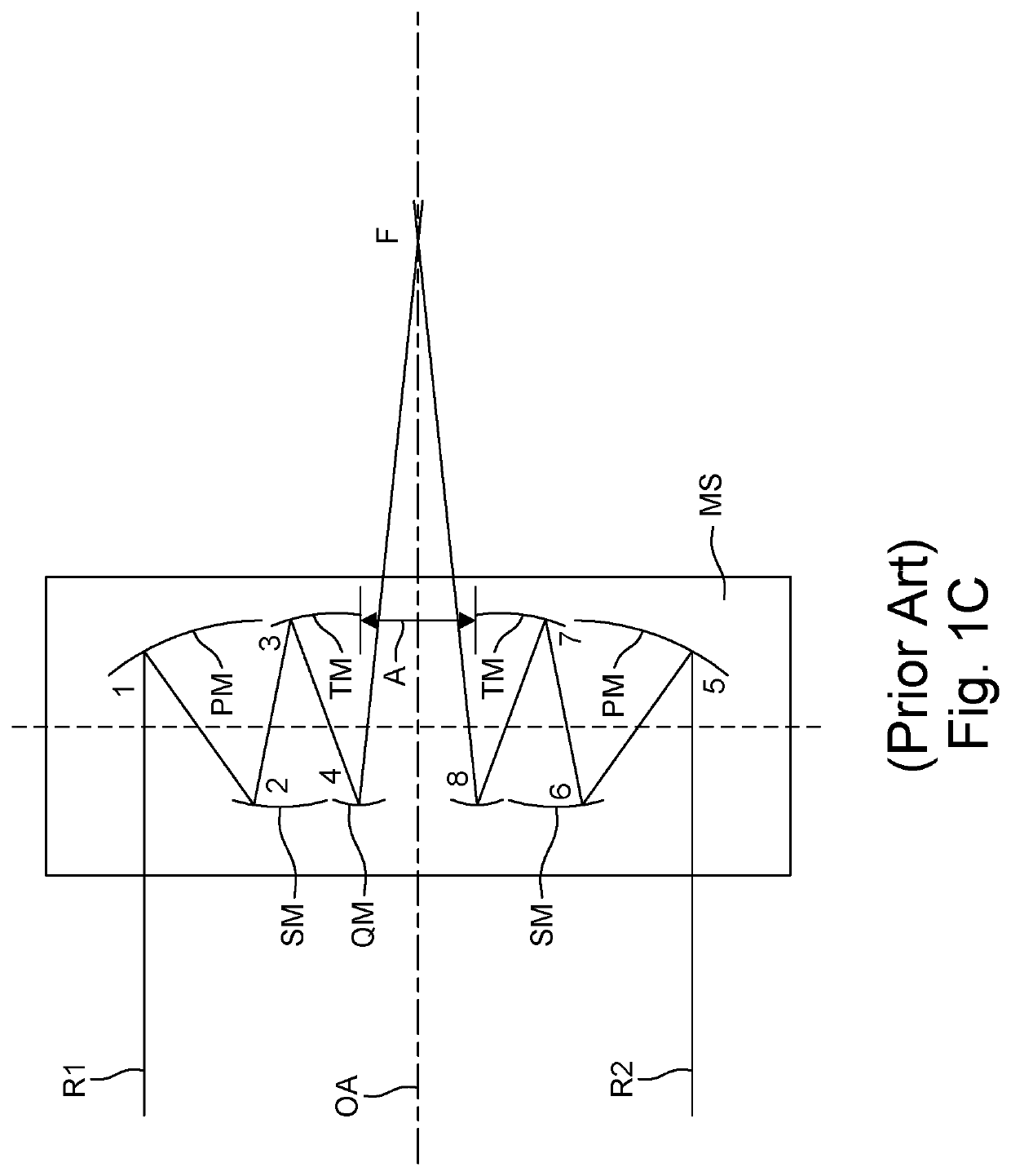
[0011]In general, according to one aspect, the invention features an optical system, comprising a first mirror substrate having a primary mirror and a tertiary mirror and a second mirror substrate opposing the first mirror substrate and having a secondary mirror and a quaternary mirror. Then, at least one mirror of only one of the mirror substrates is aspheric and the mirrors of the other mirror substrate are flat or spherical. In this way, the system is rendered more robust and tolerant to thermal and vibration effects. It can also be provide reduced manufacturing tolerances.

Problems solved by technology

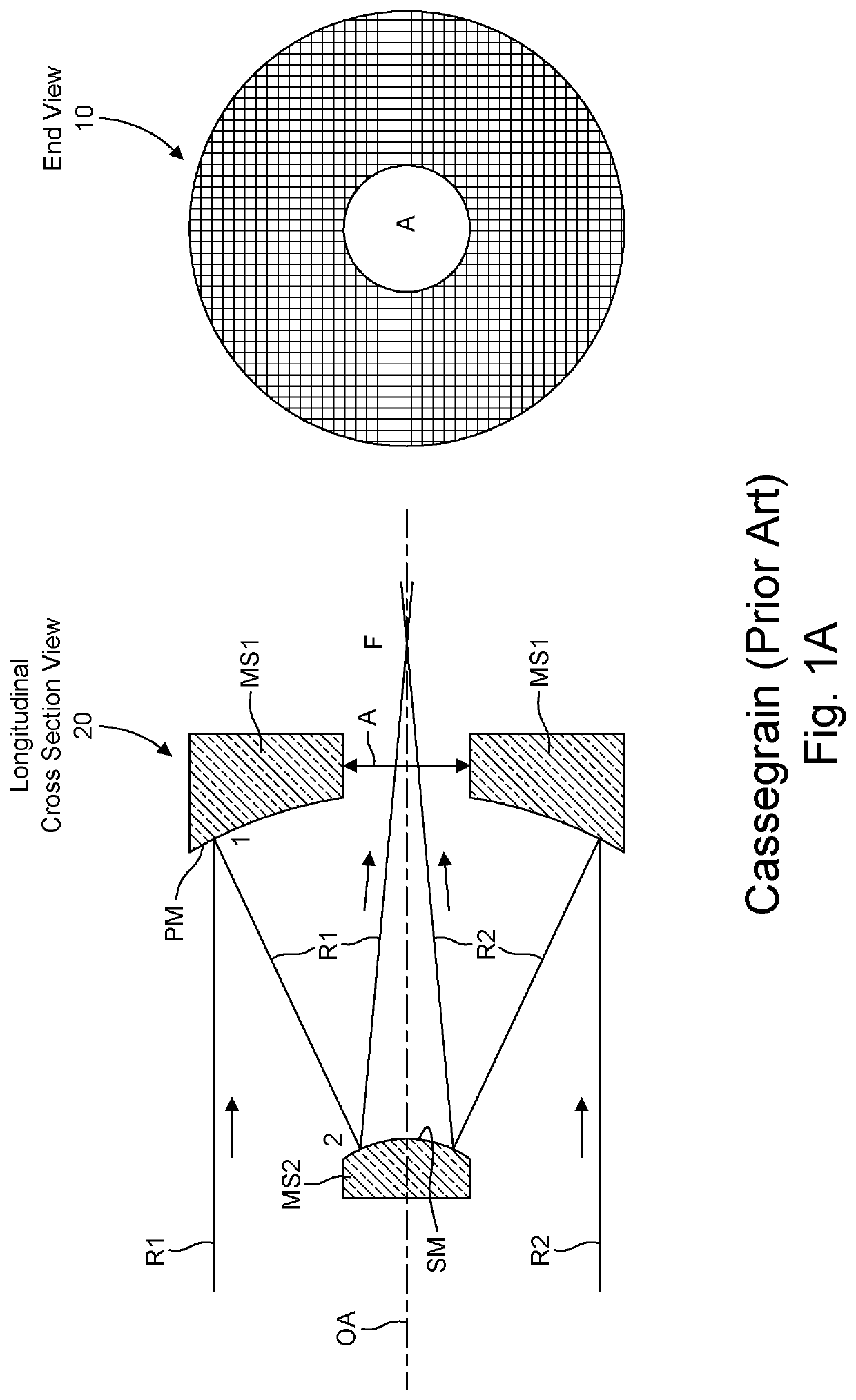
While refractive lenses in telescopes have many advantages, they do suffer from chromatic aberration.
Creating an image cube from multiple images is not an easy task as each sensor for each spectral band may have its own pixel size and viewing direction.

Method used


Image

  • Multi-channel folded optical system
  • Multi-channel folded optical system
  • Multi-channel folded optical system

Examples


Embodiment Construction

[0035]The invention now will be described more fully hereinafter with reference to the accompanying drawings, in which illustrative embodiments of the invention are shown. This invention may, however, be embodied in many different forms and should not be construed as limited to the embodiments set forth herein; rather, these embodiments are provided so that this disclosure will be thorough and complete, and will fully convey the scope of the invention to those skilled in the art.

[0036]As used herein, the term “and / or” includes any and all combinations of one or more of the associated listed items. Further, the singular forms and the articles “a”, “an” and “the” are intended to include the plural forms as well, unless expressly stated otherwise. It will be further understood that the terms: includes, comprises, including and / or comprising, when used in this specification, specify the presence of stated features, integers, steps, operations, elements, and / or components, but do not pre...


PUM

PropertyMeasurementUnit
dielectricaaaaaaaaaa
chromatic aberrationaaaaaaaaaa
massaaaaaaaaaa

Abstract

An optical system such as an imaging system, projecting system or combined imaging and projecting system, has complex dielectric coatings and / or reflecting polarizers to separate multiple spectral bands and / or polarizations on one or more of the system's curved mirrors.

Description

RELATED APPLICATIONS[0001]This application claims the benefit under 35 USC 119(e) of U.S. Provisional Application No. 62 / 690,645, filed on Jun. 27, 2018, which is incorporated herein by reference in its entirety.BACKGROUND OF THE INVENTION[0002]While refractive lenses in telescopes have many advantages, they do suffer from chromatic aberration. Therefore, many newer telescope designs, especially telescopes operating across wide spectral bands or operating in spectral bands where refractive optics become expensive, rely heavily on reflective surfaces, both aspheric, spherical, and flat, for sharper focusing and ease of manufacturing. Moreover, reflective telescopes can have lower mass than refractive ones.[0003]The designs can be made athermal (i.e., insensitive to temperature fluctuations) by fabricating telescope components from material that responds to temperature fluctuations negligibly (low thermal coefficient of expansion) or identically to temperature fluctuations in terms of...

Claims


Application Information

Patent Timeline
Patent Type & Authority Patents(United States)
IPC IPC(8): G02B23/02G02B17/08H04N5/225G02B5/08
CPCG02B23/02G02B5/0825G02B17/0808H04N5/2254H04N5/2258G02B17/0824H04N23/45H04N23/55
Inventor SINCLAIR, MATTHEW A.BOHN, PAUL AARONLAINE, JUHA-PEKKAROGOMENTICH, FRANCIS J.
Owner CHARLES STARK DRAPER LABORATORY
Why Eureka
Try Eureka