
Active thermal management system for electronic devices and method of achieving device-to-device isothermalization

a technology of active thermal management and electronic devices, applied in the direction of cooling/ventilation/heating modifications, semiconductor/solid-state device details, and modifications by conduction heat transfer, can solve the problems of varying hot spots, devices operating with variable losses, and electrical thermal obstacles to realize the full potential of wide-band gap devices, and achieve the effect of minimizing the temperature differential (t)

Active Publication Date: 2022-04-05
THE BOARD OF TRUSTEES OF THE UNIV OF ILLINOIS
View PDF25 Cites 0 Cited by
  • Summary
  • Abstract
  • Description
  • Claims
  • Application Information

AI Technical Summary

Benefits of technology

This approach reduces thermomechanical stresses and improves reliability by achieving device-to-device isothermalization, enhancing the performance and efficiency of high power density electronic systems by minimizing temperature differentials and optimizing heat dissipation.

Problems solved by technology

However, the compact layout to reduce the volume and weight of the system and the high level of integration with passive components creates electro-thermal obstacles for realizing the full potential of wide bandgap devices.
Electronic devices operating with variable losses can generate spatially and temporally varying hot spots, which cannot be mitigated with traditional thermal management approaches.
Yet, these conventional methods can be stymied by the temperature variation between multiple electronic devices on the same module.
Previous research has shown that over-temperature and thermal-cycling induced failures are the most common failure modes for power electronic modules.
The thermomechanical stresses in the power module can damage the interfaces and connections between semiconductor components, which can reduce reliability due to thermomechanical failures.

Method used


Image

  • Active thermal management system for electronic devices and method of achieving device-to-device isothermalization
  • Active thermal management system for electronic devices and method of achieving device-to-device isothermalization
  • Active thermal management system for electronic devices and method of achieving device-to-device isothermalization

Examples


example 1

Switchable Heat Spreader with Liquid Metal Droplet

[0042]In a first example, two GaN devices are integrated with a liquid metal-based heat spreader as described below. By precisely controlling the location of the liquid metal droplet in the internal channel, variable thermal pathways to the front side of the heat spreader can be obtained and—at some optimal set point depending on the GaN device temperature mismatch—temperature equilibration. The length of the liquid metal droplet employed for this example is longer than the length of the two GaN devices, which are closely spaced apart, as shown in the schematic of FIG. 2. Thus, the liquid metal droplet may be positioned adjacent to both GaN devices simultaneously.

[0043]To fabricate the heat spreader of this example, two top-cooled EPC 2034 GaN devices (Efficient Power Conversion Corporation), each having dimensions of 2.6 mm×4.6 mm×0.7 mm, are soldered onto a single printed circuit board (PCB) having dimensions of 40 mm×40 mm×1.6 mm....

example 2

Switchable Heat Spreader with Metal Slider

[0048]Finite element simulations using a solid-phase thermally conductive body (“slider”) movably positioned in the internal channel are used to predict the temperature distribution within the heat spreader and the effect of slider position on temperature and heat flux.

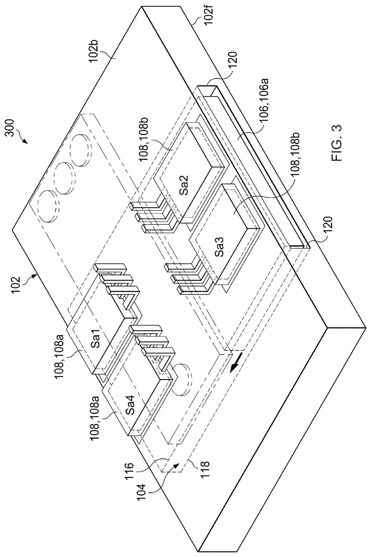
[0049]Referring to FIG. 3, the switchable heat spreader of this example comprises alumina with a movable copper slider in the internal channel. The heat spreader has dimensions of 107 mm×153 mm×10 mm. The internal channel has dimensions of 107 mm×80 mm×8 mm. The slider moving in the channel has a transverse cross-sectional area of 80 mm×8 mm. The slider position and size can be modified as inputs to the simulations. Electronic devices are introduced to the model as concentrated heat sources labeled Sa1, Sa2, Sa3, Sa4, where Sa1 and Sa4 are disposed in opposition to Sa2 and Sa3, respectively, on the heat spreader, adjacent to the internal channel. The system layout can be creat...


PUM


Abstract

An active thermal management system for electronic devices comprises: a heat spreader having an internal channel; a thermally conductive body moveably positioned in the internal channel; and two or more electronic devices in thermal contact with a back surface of the heat spreader and positioned adjacent to the internal channel. A location of the thermally conductive body within the internal channel determines a path for heat flow from the back surface to a front surface of the heat spreader. The location of the thermally conductive body within the internal channel may be selected to minimize a temperature differential (ΔT) between the electronic devices.

Description

RELATED APPLICATION[0001]The present patent document claims the benefit of priority under 35 U.S.C. § 119(e) to U.S. Provisional Patent Application No. 62 / 649,134, filed on Mar. 28, 2018, which is hereby incorporated by reference in its entirety.FEDERALLY SPONSORED RESEARCH OR DEVELOPMENT[0002]This invention was made with government support under grant number 1449548 awarded by the National Science Foundation. The government has certain rights in the invention.TECHNICAL FIELD[0003]The invention is related generally to thermal management of electronic devices and more particularly to an approach for active thermal management in high power density electronic systems.BACKGROUND[0004]Power electronics having increased volumetric and gravimetric power density are required for various applications, such as mobile systems in all-electric or plug-in hybrid electric vehicles. The utilization of wide-bandgap semiconductor materials such as silicon carbide (SiC) and gallium nitride (GaN) with ...

Claims


Application Information

Patent Timeline
Patent Type & Authority Patents(United States)
IPC IPC(8): H05K7/20H01L23/473H01L23/367
CPCH05K7/20945H01L23/367H01L23/473H05K7/209H05K7/20254H05K7/20509H05K7/20927H01L23/42H01L23/3736H01L23/46H05K7/20518H05K7/20872
Inventor KING, WILLIAM P.MILJKOVIC, NENADWEISENSEE, PATRICIA BKWON, BEOMJINYANG, TIANYU
Owner THE BOARD OF TRUSTEES OF THE UNIV OF ILLINOIS
Features
  • Generate Ideas
  • Intellectual Property
  • Life Sciences
  • Materials
  • Tech Scout
  • Unparalleled Data Quality
  • Higher Quality Content
  • 60% Fewer Hallucinations
Learn More