Pressure sensor with improved measurement accuracy

a technology of pressure sensor and measurement accuracy, applied in the field of pressure sensors, can solve the problems of limited material and structure used for pressure sensors for sanitary use, and is not easy to meet all performance requirements of such pressure sensors

Active Publication Date: 2022-05-24
YAMATAKE HONEYWELL CO LTD
View PDF3 Cites 0 Cited by
  • Summary
  • Abstract
  • Description
  • Claims
  • Application Information

AI Technical Summary

Benefits of technology

[0009]The present disclosure has been developed so as to address the problems described above with an object of providing a pressure sensor that has high pressure resistance performance and small measurement error by suppressing hysteresis with respect to pressure, in which the sensitivity with respect to pressure fluctuations in the fluid (referred to below as a “measurement target fluid”) to be measured is improved by reviewing the structure of the diaphragm itself.
[0020]According to the present disclosure, it is possible to provide a pressure sensor that has a high pressure resistance performance and suppressed measurement error by suppressing hysteresis with respect to pressure, and is highly sensitive to pressure fluctuations in the measurement target fluid.

Problems solved by technology

As described above, the materials and structures used for pressure sensors for sanitary usage are limited as compared with other pressure sensors.
Accordingly, it is not easy to meet all performance requirements for such pressure sensors at a high level.
As described above, the demands for the rigidity of a diaphragm depend on the performance requirements, and these different demands are contradictory to each other (in particular, the suppression of measurement error by reduction in hysteresis is contradictory to the improvement of the sensor sensitivity).

Method used


Image

  • Pressure sensor with improved measurement accuracy
  • Pressure sensor with improved measurement accuracy
  • Pressure sensor with improved measurement accuracy

Examples


first embodiment

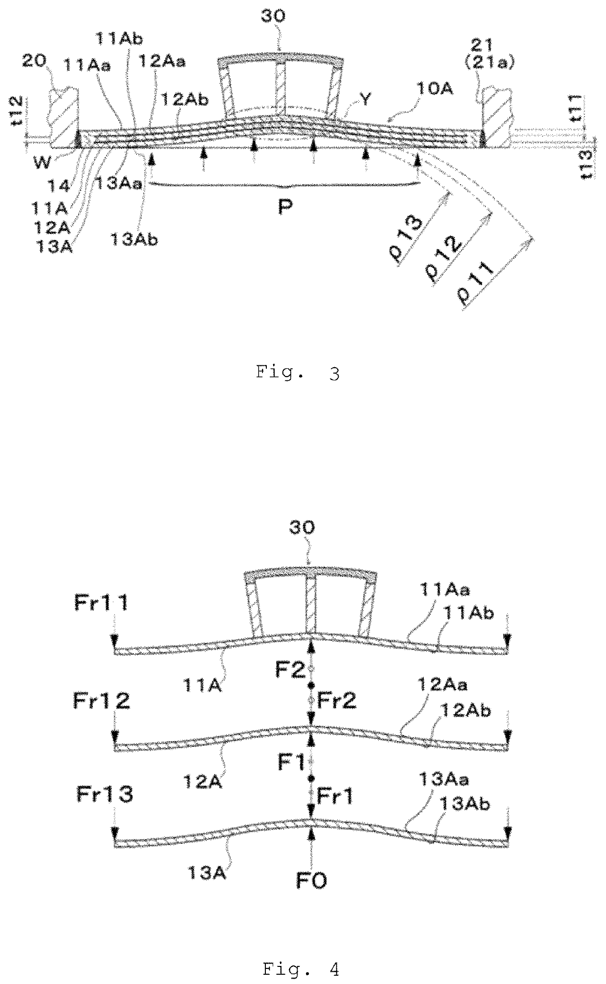
[0032]First, a pressure sensor LA having a diaphragm unit 10A according to a first embodiment of the present disclosure will be described with reference to FIG. 1 and FIG. 2.

[Structure of the Pressure Sensor]

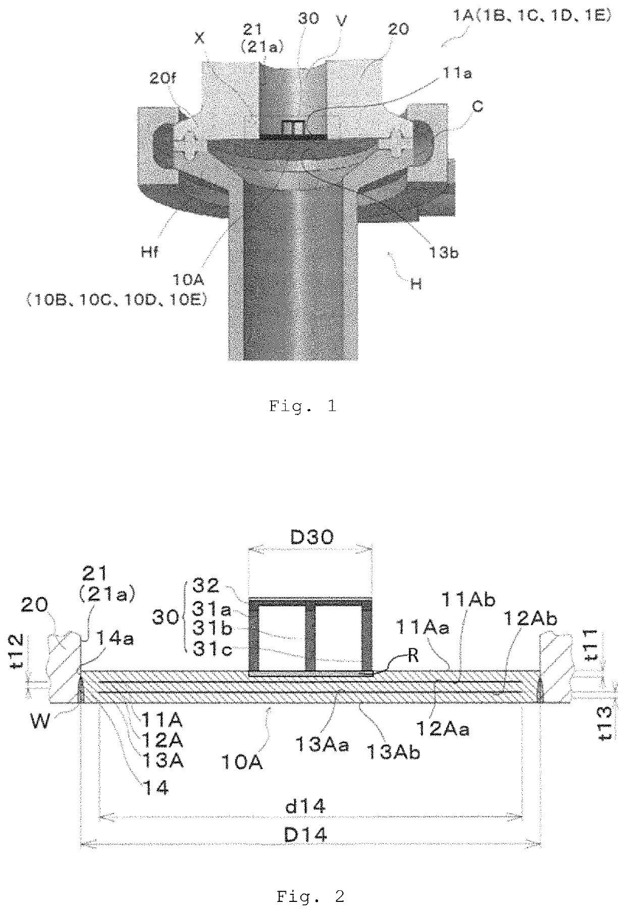
[0033]First, the structure of the pressure sensor 1A will be described with reference to FIG. 1 and FIG. 2. As illustrated in FIG. 1, this pressure sensor 1A mainly includes the diaphragm unit 10A that is deformed (deflected) by receiving a pressure P of a measurement target fluid F, a housing 20 that is coupled to the outer peripheral edge of this diaphragm unit 10A and supports the diaphragm unit, and a sensing unit 30 that detects the deformation of the diaphragm unit 10A as a predetermined electric signal (for example, a voltage signal). In addition, below the housing 20, a pipe H through which the measurement target fluid F flows in and out is attached via, for example, a clamp C.

10A>

[0034]The diaphragm unit 10A is an element including thin film members that change in the d...

second embodiment

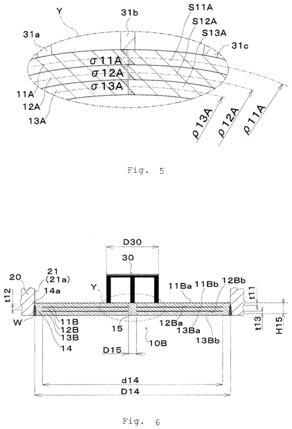
[0066]Next, a pressure sensor 1B according to a second embodiment of the present disclosure will be described. The structure of this pressure sensor 1B is the same as that of the pressure sensor 1A according to the first embodiment except that the diaphragm unit 10A included in the pressure sensor 1A is replaced with a diaphragm unit 10B illustrated in FIG. 6. The structure of the diaphragm unit 10B will be described below.

10B>

[0067]As illustrated in FIG. 6, the diaphragm unit 10B includes a non-deformed portion 15 that has high rigidity and is provided in the center portion, and a first thin plate member 11B, a second thin plate member 12B, and a third thin plate member 13B that have low rigidity and are provided so as to surround the peripheral edge of this non-deformed portion 15. The first thin plate member 11B, the second thin plate member 12B, and the third thin plate member 13B are formed in cylindrical thin plates, the inner peripheral edges thereof are connected to the oute...

third embodiment

[0072]Next, a pressure sensor 1C according to a third embodiment of the present disclosure will be described. The structure of this pressure sensor 1C is the same as that of the pressure sensor 1A according to the first embodiment except that the diaphragm unit 10A included in the pressure sensor 1A is replaced with a diaphragm unit 10C illustrated in FIG. 8. The structure of the diaphragm unit 10C will be described below.

10C>

[0073]The diaphragm unit 10C has the same basic form as the diaphragm unit 10A, but differs from the diaphragm unit 10A in that, as illustrated in FIG. 8, recesses are formed in the lower surfaces of a first thin plate member 11C and a second thin plate member 12C constituting the diaphragm unit 10C, that is, a first lower surface 11Cb and a second lower surface 12Cb. Since the recesses are formed, spaces C1 and C2 are formed between two adjacent thin plate members, that is, between the first thin plate member 11C and the second thin plate member 12C, and betwe...


PUM

PropertyMeasurementUnit
pressureaaaaaaaaaa
corrosion resistanceaaaaaaaaaa
heataaaaaaaaaa

Abstract

To provide a pressure sensor that has high pressure resistance performance, small measurement error by suppressing hysteresis with respect to pressure, and high sensitivity and high productivity, a pressure sensor includes a diaphragm unit with a first main surface that receives a measurement target fluid's pressure and a second main surface located on the opposite side of this first main surface, a housing, and a sensing unit that outputs the diaphragm unit's deformation as an electric signal, in which at least part of the diaphragm unit has a multi-layer structure in which a plurality of thin plate members are stacked, and the plurality of thin plate members are deformed independently of each other while at least part of the plurality of thin plate members is in press-contact to each other in a pressure receiving state in which the measurement target fluid's pressure is applied to the first main surface.

Description

CROSS REFERENCE TO RELATED APPLICATIONS[0001]This patent application claims the benefit of foreign priority to Japanese Patent Application No. JP 2020-026177 filed on Feb. 19, 2020, the disclosure of which is hereby incorporated by reference in its entirety.BACKGROUND OF THE INVENTION[0002]The present disclosure relates to a pressure sensor that detects the pressure of a fluid or the like and, more particularly, to a pressure sensor for sanitary usage.[0003]Of pressure sensors that detect the pressure of a fluid, pressure sensors for sanitary usage used at manufacturing sites in fields of food and pharmaceuticals need hygienic consideration, so stringent requirements are imposed on corrosion resistance, cleanliness, reliability, versatility, and the like. These demands have become even more stringent in recent years when laws and regulations regarding hygiene management have been tightened.[0004]Under the circumstances surrounding such pressure sensors for sanitary usage, to meet, f...

Claims


Application Information

Patent Timeline
Patent Type & Authority Patents(United States)
IPC IPC(8): G01L9/00G01L7/08
CPCG01L7/082G01L9/0041G01L9/0051G01L9/0044G01L9/0052
Inventor SETO, YUKIOGASAWARA, RINANIIMURA, YUSUKE
Owner YAMATAKE HONEYWELL CO LTD
Why Eureka
Try Eureka