
Process for manufacturing an optoelectronic device having a diode matrix

a manufacturing process and diode technology, applied in the direction of solid-state devices, basic electric elements, electric devices, etc., can solve the problems of reducing the crystal quality of the semiconductor stack, and reducing the efficiency of the diode. , to achieve the effect of allowing the risk of degradation of the crystal quality of the compound semiconductor

Active Publication Date: 2022-06-28
COMMISSARIAT A LENERGIE ATOMIQUE ET AUX ENERGIES ALTERNATIVES
View PDF10 Cites 1 Cited by
  • Summary
  • Abstract
  • Description
  • Claims
  • Application Information

AI Technical Summary

Benefits of technology

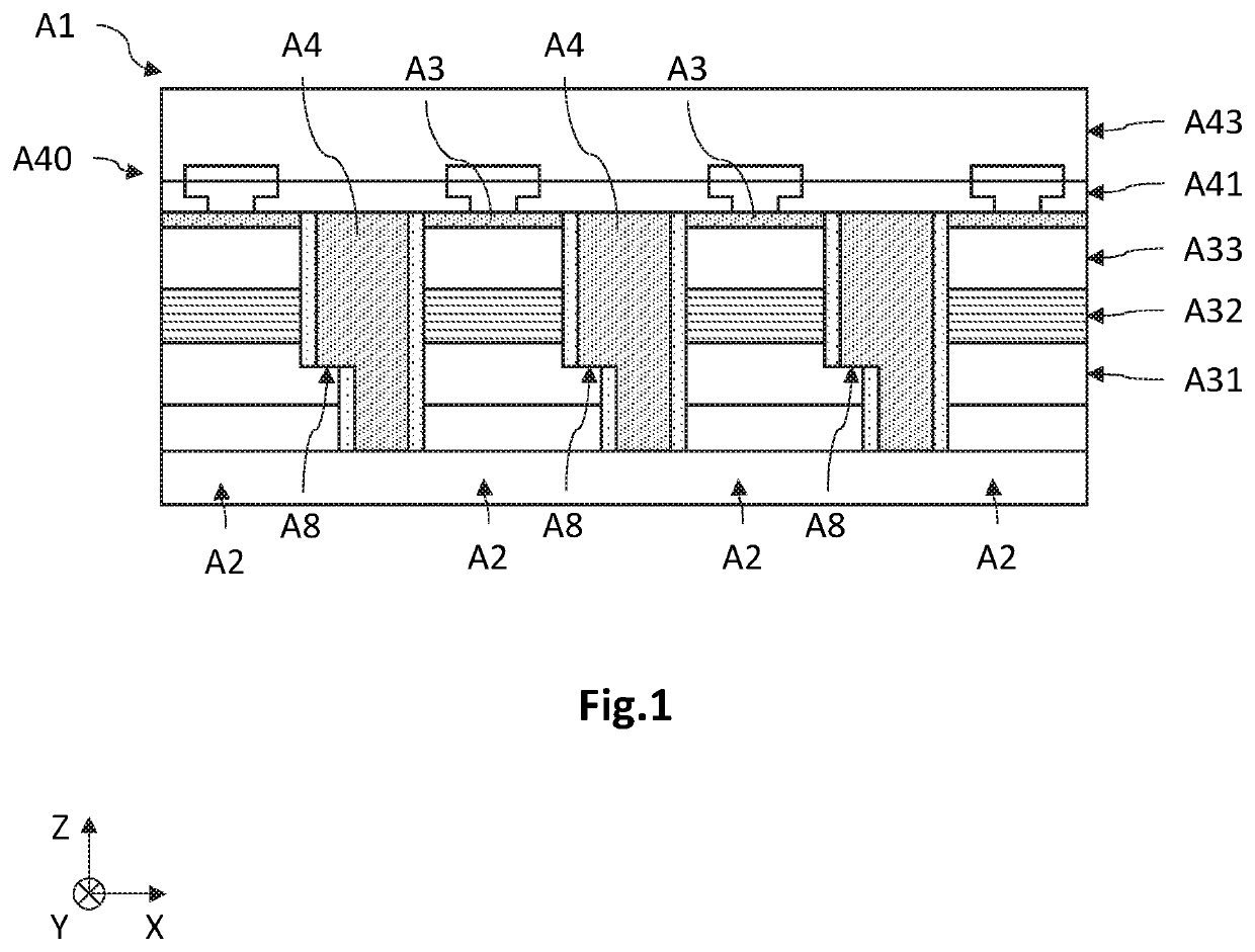
The goal of this patent is to improve the process for making optoelectronic devices with diodes. The new process helps prevent the quality of the material on which the diodes are based from becoming poor. This improves the overall quality of the device.

Problems solved by technology

However, the process for fabricating this optoelectronic device has the drawback of requiring a step of localized etching of the doped two-dimensional semiconductor layers and of the active layer, with the aim of pixelating the diodes.
Now, this etching step may lead to the formation of defects, especially on the etched flanks, these defects being liable to degrade the performance of the diodes, insofar as incorrect or insufficient passivation of the flanks may result in leakage.
Moreover, the difference in lattice parameter between the growth substrate and the epitaxially grown semiconductor layers may cause crystal defects to form, notably threading dislocations that extend in the direction of growth, thus degrading the crystal quality of the semiconductor stack, and therefore degrading the performance of the diodes.
In addition, during the cooling after the epitaxial growth step, the difference in coefficient of thermal expansion between the growth substrate and the semiconductor stack, for example between the silicon of the substrate and the nitride-based semiconductor, may generate a high tensile mechanical stress in the semiconductor stack, this stress being liable to cause cracks to appear in the semiconductor stack, or to cause the wafer to bend greatly.

Method used


Image

  • Process for manufacturing an optoelectronic device having a diode matrix
  • Process for manufacturing an optoelectronic device having a diode matrix
  • Process for manufacturing an optoelectronic device having a diode matrix

Examples


Embodiment Construction

[0052]In the figures and in the remainder of the description, the same references have been used to designate identical or similar elements. In addition, the various elements are not shown to scale for the sake of clarity of the figures. Unless indicated otherwise, the terms “substantially,”“about,” and “on the order of” mean to within 10%. Moreover, the expression “comprising a” should be understood to mean “comprising at least one,” unless indicated otherwise.

[0053]Embodiments of the present disclosure relate to a process for fabricating an optoelectronic device 1 comprising a matrix-array of diodes 2. These may be light-emitting diodes or photodiodes.

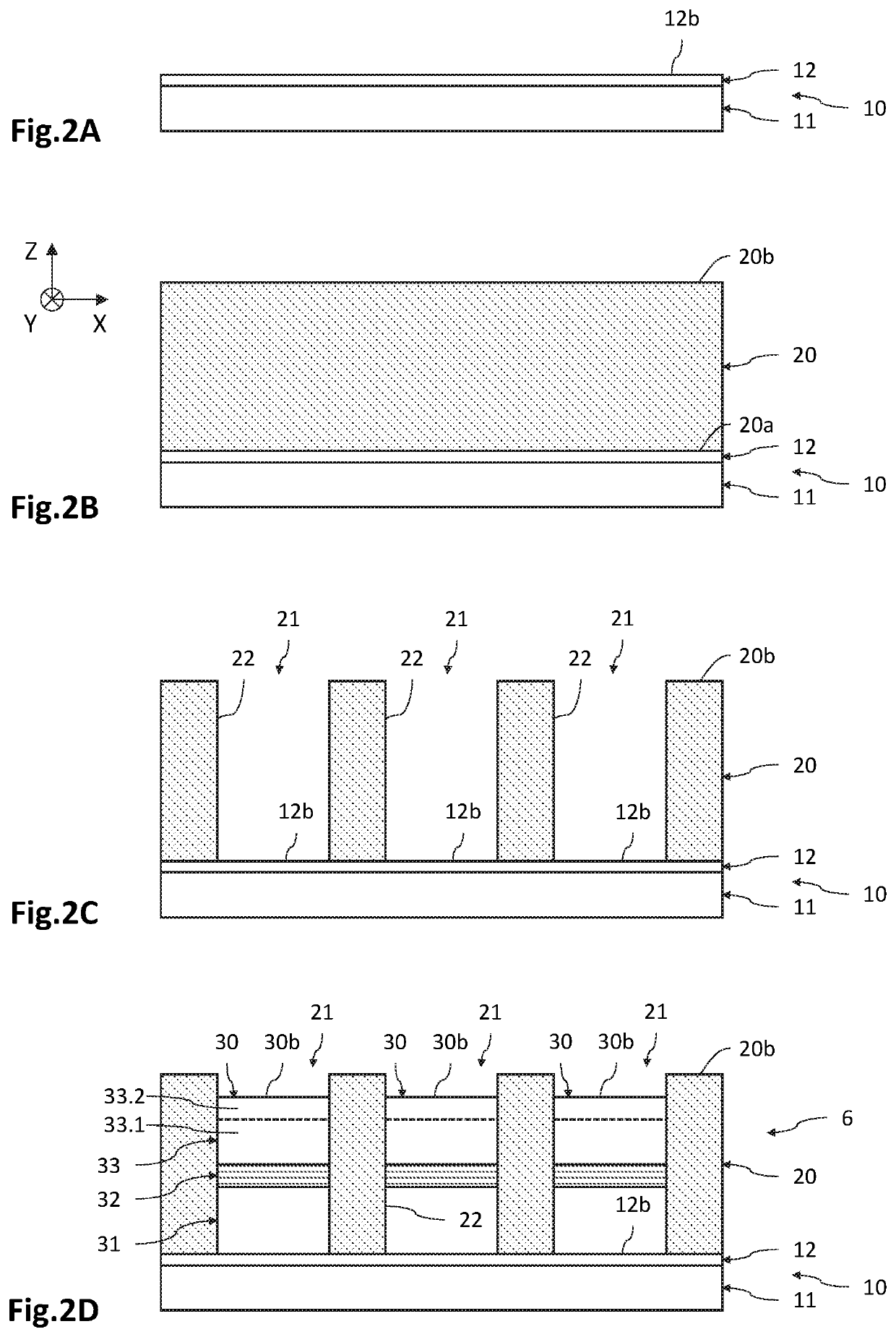
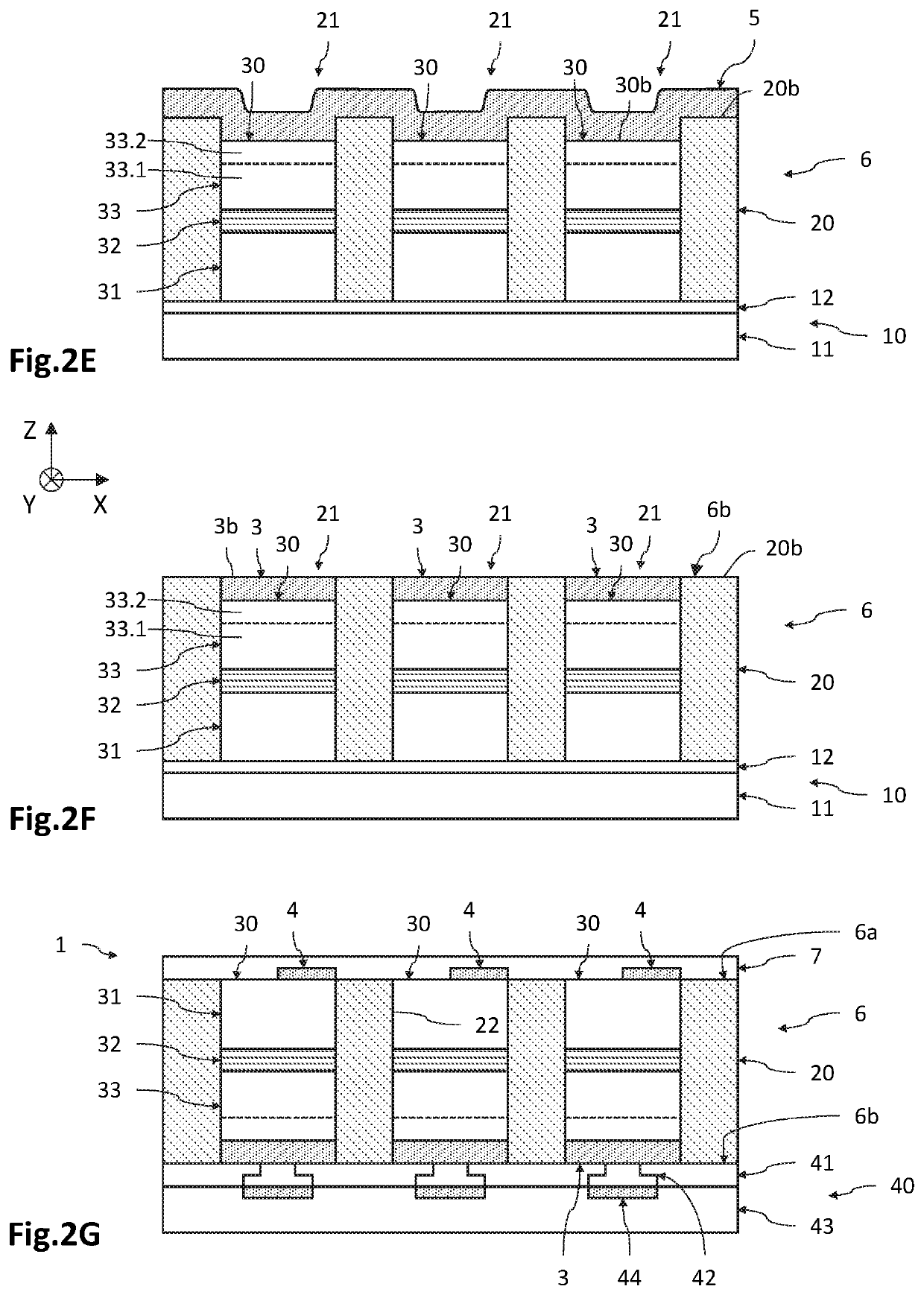
[0054]FIGS. 2A to 2G are schematic and partial views, in cross section, of an embodiment of the process for fabricating an optoelectronic device 1 comprising a matrix-array of diodes 2. In this example, the diodes 2 are light-emitting diodes and are made based on GaN from a growth substrate 10 made based on silicon.

[0055]An orthogona...


PUM

PropertyMeasurementUnit
thicknessaaaaaaaaaa
thickness emcaaaaaaaaaa

Abstract

A process for manufacturing an optoelectronic device having a diode matrix with semiconductor stacks involves providing a growth substrate having a support substrate coated with a nucleation layer defining a nucleation surface. A dielectric layer is deposited on the nucleation surface. A plurality of through-holes, extending to the nucleation surface, are formed in the dielectric layer. The nucleation layer, located in the through-holes, is etched to free up an upper surface of the support surface and expose a lateral surface of the nucleation layer forming a lateral nucleation surface. A dielectric region is formed extending in the support substrate such that, during a subsequent epitaxial growth stage, each first doped portion is formed especially from the lateral nucleation surface. In the through-holes and from the nucleation surface, the semiconductor stacks are epitaxially grown such that at least the first doped portions and active zones thereof are located in the through-holes.

Description

CROSS-REFERENCE TO RELATED APPLICATIONS[0001]This application is a national phase entry under 35 U.S.C. § 371 of International Patent Application PCT / FR2019 / 050913, filed Apr. 17, 2019, designating the United States of America and published as International Patent Publication WO 2019 / 202258 A2 on Oct. 24, 2019, which claims the benefit under Article 8 of the Patent Cooperation Treaty to French Patent Application Serial No. 1853495, filed Apr. 20, 2018.TECHNICAL FIELD[0002]The field of the present disclosure is that of optoelectronic devices comprising a matrix-array of light-emitting diodes or photodiodes. The disclosure notably applies to the field of lighting devices, display screens and image projectors, and to the field of photodetectors and sensors.BACKGROUND[0003]Optoelectronic devices comprising a matrix-array of light-emitting diodes suitable for forming lighting devices, display screens or image projectors already exist.[0004]Thus, document EP2960940 illustrates an example ...

Claims


Application Information

Patent Timeline
Patent Type & Authority Patents(United States)
IPC IPC(8): H01L33/00H01L33/22H01L33/14H01L33/20H01L21/02H01L33/12H01L27/15H01L27/144
CPCH01L33/0093H01L21/0254H01L21/02381H01L21/02639H01L21/02647H01L27/1446H01L27/153H01L33/007H01L33/12H01L33/14H01L33/20H01L33/22H01L21/02458H01L25/167H01L2933/0016
Inventor CHARLES, MATTHEW
Owner COMMISSARIAT A LENERGIE ATOMIQUE ET AUX ENERGIES ALTERNATIVES
Learn More