Acquisition method, acquisition device, and control program for tomographic image data by means of angular offset

a control program and tomographic image technology, applied in tomography, x/gamma/cosmic radiation measurement, instruments, etc., can solve the problems of large computational resources, large computation scale, and large computational resources, and achieve the quality of reconstructed images in which various artifacts are readily developed compared to ir, and achieve the effect of reducing the cost of reconstructed images

Active Publication Date: 2022-07-05
RIKEN +1
View PDF39 Cites 0 Cited by
  • Summary
  • Abstract
  • Description
  • Claims
  • Application Information

AI Technical Summary

Benefits of technology

[0017]In certain aspects of the present disclosure, a high-definition and high-quality reconstructed image can be acquired at a high speed while using a relatively small computational resources.

Problems solved by technology

In conventional ARTs, a calculation scale becomes huge and a large amount of computational resources are required.
The FBP is, however, generally disadvantageous in the quality of reconstructed images in which various artifacts are readily developed compared to IR.

Method used


Image

  • Acquisition method, acquisition device, and control program for tomographic image data by means of angular offset
  • Acquisition method, acquisition device, and control program for tomographic image data by means of angular offset
  • Acquisition method, acquisition device, and control program for tomographic image data by means of angular offset

Examples


Embodiment Construction

[0030]The embodiments of tomographic imaging according to the present disclosure will be described herein with reference to the accompanying drawings. For all drawings, the common reference numerals are given to common part or element unless otherwise noted. In addition, each element in the drawing should be understood as not being drawn to scale.

1. The Principle

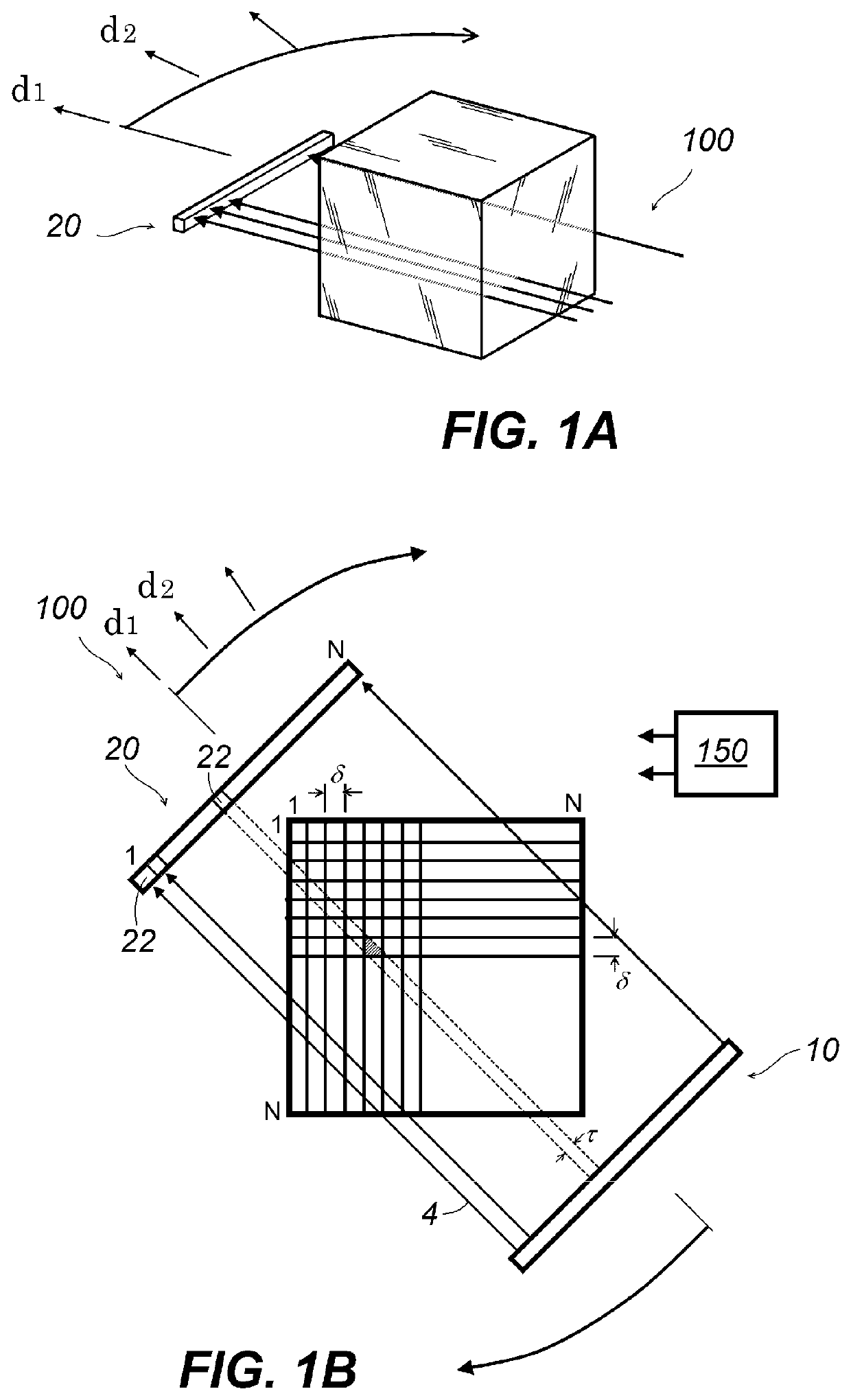
[0031]The illustrative geometric configuration in the present embodiment will be described. FIG. 1A and FIG. 1B are schematic diagrams for illustrating a schematic configuration including a planar arrangement at a cutting plane of the object for which an image is captured, in one example tomographic imaging device 100 where an image of the present embodiment is acquired. A group of pixels having N pixels×N pixels in a plane in the space that is fixed to the object (not shown in FIG. 1A and FIG. 1B) is defined. Typically, the integer N is made to coincide with the number of detection elements 22 of the detection device 20. Fo...


PUM


Abstract

In an embodiment of the present disclosure, in order to raise the reproducibility of a reconstructed tomographic image without increasing a calculation load, any one among two directions adjacent to two boundaries that demarcate an angular scan range is offset from any one among coordinate axes of a two-dimensional tomographic image of N pixels×N pixels, and the angle of the offset is made to be above 0 degrees and under 90 degrees or above −90 degrees and under 0 degrees. A detection device, which includes N detection elements, performs detection in each detection direction, and a first vector having N×N elements is obtained from a detection signal obtained by the detection device in a detection operation. A discrete Inverse Radon transform matrix is applied to the first vector to obtain a second vector having N×N elements. The second vector is de-vectorized to obtain image data for a two-dimensional tomographic image of N pixels×N pixels. An inverse matrix of a system matrix for an offset is obtained and used as the discrete Inverse Radon transform matrix.

Description

BACKGROUNDTechnical Field[0001]The present disclosure relates to a method for acquiring tomographic image data, an acquisition apparatus, and a control program by an angle offset. More particularly, the present disclosure relates to a method of acquiring tomographic image data, an acquisition apparatus, and a control program that incorporate an efficient algebraic method of discrete inverse Radon transform based on an angle offset.Description of the Related Art[0002]Tomography, or a tomographic imaging method using waves or particles having transmission nature such as X-rays, gamma rays, light waves, or waves or particles exhibiting any sort of permeability or transmission ability such as a seismic wave or other has been put into practical use. Typical examples include an X-ray CT scanner used in medical and industrial applications, SPECT (Single Photon Emission Computed Tomography), and Optical Tomography. In recent years, an optical CT device using visible light has been developed...

Claims


Application Information

Patent Timeline
Patent Type & Authority Patents(United States)
IPC IPC(8): A61B6/03G06T11/00A61B6/00
CPCA61B6/4241A61B6/032A61B6/5205G06T11/008G01T1/161A61B6/03G06F17/16G06T1/00A61B6/037G06T11/006G06T2211/436
Inventor KANDA, NAOHIROTAKANASHI, TAKAOKI
Owner RIKEN
Why Eureka
Try Eureka