Low noise oximetry cable

a low-noise, oximetry cable technology, applied in the direction of cables, insulated conductors, applications, etc., can solve the problems of difficult application and removal of graphite gel in the manufacturing process, low-level signals, and triboelectric noise in the detector signal

Active Publication Date: 2022-07-19
MASIMO CORP
View PDF1168 Cites 51 Cited by
  • Summary
  • Abstract
  • Description
  • Claims
  • Application Information

AI Technical Summary

Benefits of technology

[0009]The present disclosure describes a low noise oximetry cable that provides an improved, flexible, and durable overall construction for various medical environments. The cable can be particularly useful in environments such as emergency medical situations (EMS), where cables can undergo a tremendous amount of stress, such as repeated winding and unwinding, that can cause kinks to develop leading to or creating an electrical short in the cables. The construction of the cable described herein can reduce damage resulting from stress like repeated winding and unwinding and prevent kinks from developing. The cable can be part of a patient monitoring system that transmits real-time patient data to individual or multiple integrated or non-integrated devices.
[0010]The cable can include multiple bundles of conductors. The bundles can evenly distribute stress exerted on the conductors or cords within the cable. The bundles may be wrapped or weaved around a core that is flexible and durable. Some or all of conductors may be assembled twisted or untwisted with one or more cords. The conductors may be assembled twisted or untwisted around one or more central cores or cords.
[0014]The oximetry system of the preceding paragraph can include one or more of the following features: The noninvasive sensor can include a sensor housing configured to position an emitter and the detector proximate to the body tissue. The one or more physiological parameters can include an oxygen saturation and a pulse rate. The cable can include a core configured to reduce a tensile stress exerted on the cable and increase a durability of the cable. The core can be flexible. The first bundle and the second bundle can be twisted or weaved around the core. The first bundle can include a first shield at least partially surrounding the first plurality of wires. The cable can include a third bundle at least partially surrounded by the outer shield. The third bundle can include a third plurality of wires. The first bundle, the second bundle, and the third bundle can be twisted or weaved around a core. The first bundle and the second bundle may not be concentric with each other. The cable can include a core, and the first bundle and the second bundle may not be concentric with the core. The first bundle can include a different number of wires than the second bundle. The core can include a plurality of arcuate surfaces that contact the first bundle and the second bundle and limit an amount of contact between the first bundle and the second bundle. The plurality of arcuate surfaces can be formed at least partly by pressure from the first bundle and the second bundle on the core.
[0016]In some embodiments, a cable is disclosed that can transmit signals in an oximetry system. The cable can include a first bundle, a second bundle, and a core. The first bundle can include a first plurality of wires. The second bundle can include a second plurality of wires. The core can be configured to reduce a tensile stress exerted on the cable and increase a durability of the cable.

Problems solved by technology

The detectors of the noninvasive sensors read by many of the foregoing patient monitors generate one or more low-level signals that are susceptible to corruption from various noise, such as electromagnetic interference (EMI) and internal noise that originate in the sensor, cabling and monitors.
One internal noise source is due to a triboelectric effect, which includes static charges that build when two materials rub together.
For example, when a cable housing detector wires is flexed, impacted, or the like, the detector wires may rub together and triboelectric noise can be induced in the detector signal.
However, the graphite gel used in the manufacturing process proved difficult to apply and remove.

Method used


Image

  • Low noise oximetry cable
  • Low noise oximetry cable
  • Low noise oximetry cable

Examples


Embodiment Construction

Introduction

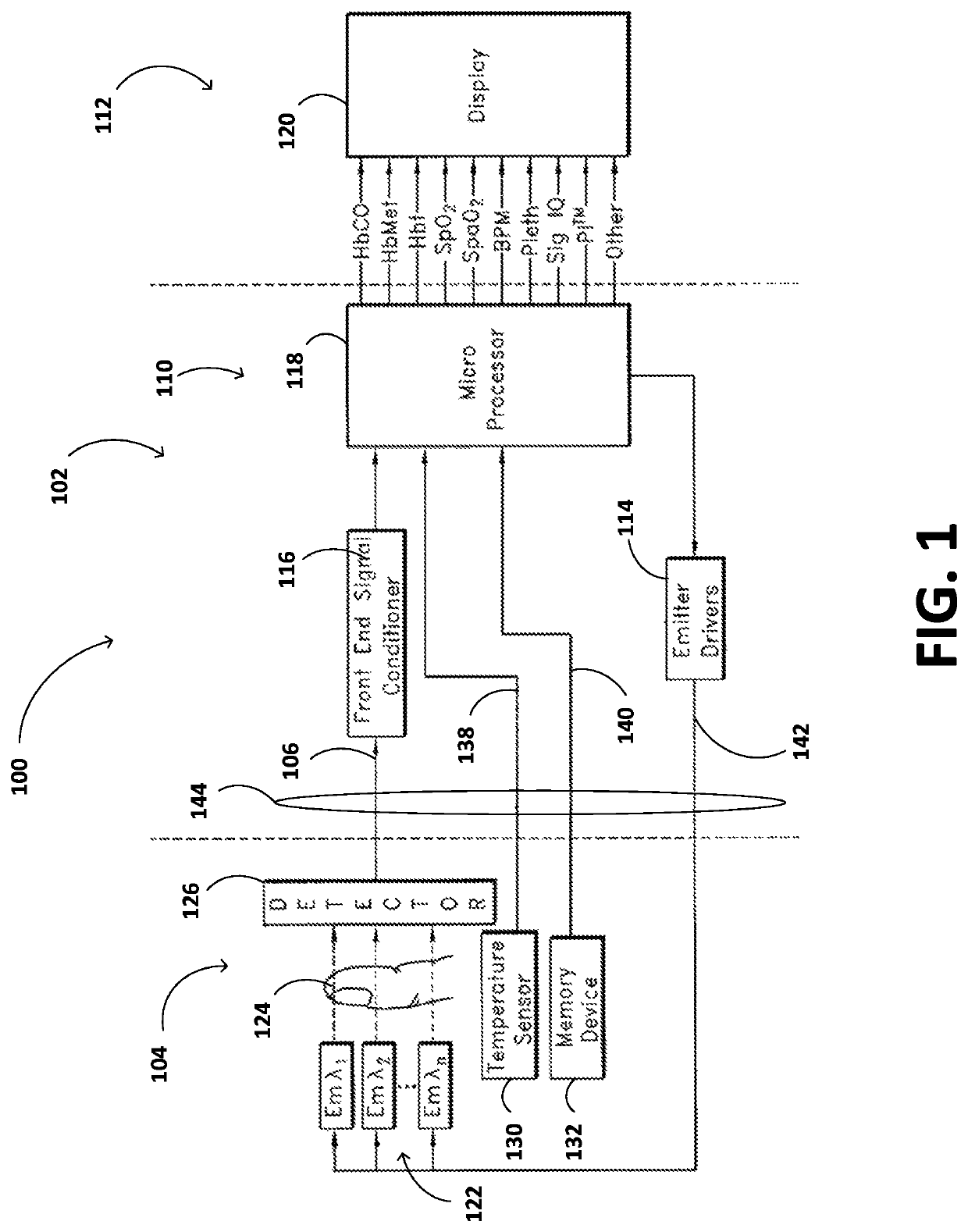
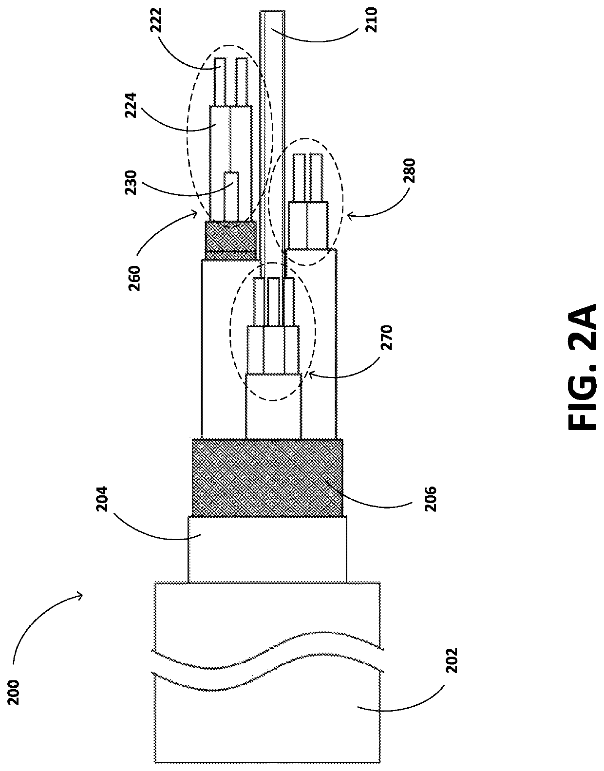
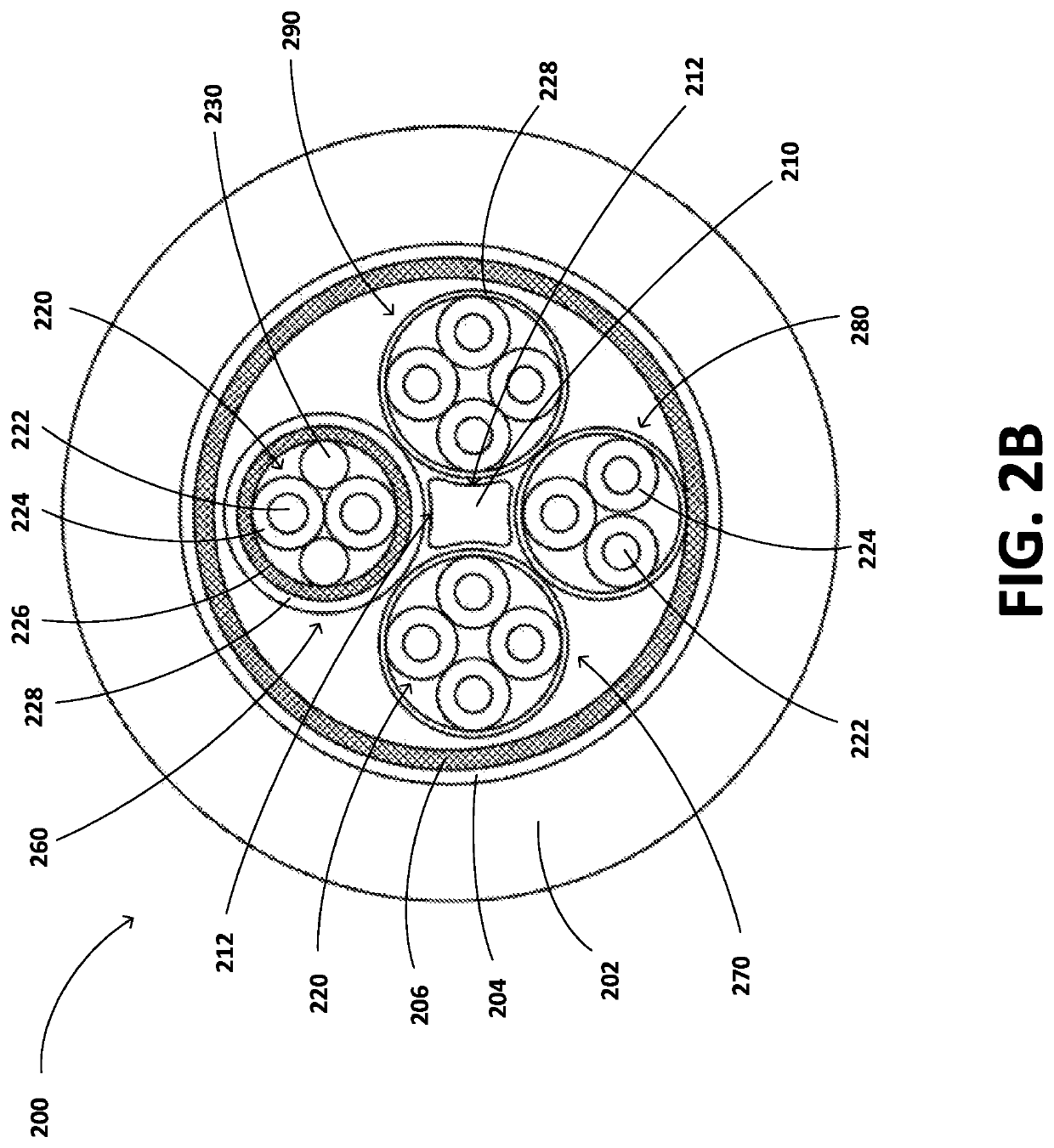
[0025]A low noise oximetry cable is provided that can communicate a low level sensitive signals between a sensor and a patient monitor. Wires or cords of the cable can be twisted within individual bundles. The individual bundles can be encased within an inner jacket that can reduce friction between different cable elements. The bundles can be encased at least partially by an inner shield that may reduce EMI between the bundles and crosstalk with other cables.

[0026]The bundles can be disposed within an outer jacket and an outer shield. The bundles can wrap around a core. The core can be placed in the center of the cable and surrounded by the bundles so that the core can absorb stress exerted on the cable and various cable elements. The core can be composed of a flexible or durable material. Two, three, four, or more bundles can wrap around the core.

[0027]A patient monitor usable with the cable disclosed herein is the Root® Platform, a patient monitoring and connectivity p...


PUM

PropertyMeasurementUnit
outer diameteraaaaaaaaaa

Abstract

The present disclosure includes a cable for a patient monitoring system. The cable can have a flexible and durable overall construction that enables the cable to withstand repeated winding and unwinding and prevent kinks from developing. The cable may include multiple bundles encased in inner jackets that reduce the amount of friction against other cable elements and allows the bundle to move more freely inside an outer jacket of the cable. The multiple bundles may include multiple wires or cords. The cable can include a flexible core that runs through the middle of the cable. The multiple bundles can be twisted, weaved, or untwisted around the core.

Description

RELATED APPLICATIONS[0001]Any and all applications for which a domestic priority claim is identified in the Application Data Sheet of the present application are hereby incorporated by reference under 37 CFR 1.57.BACKGROUNDField of the Disclosure[0002]The disclosure relates to improving the performance of patient monitors through low noise cabling.Description of the Related Art[0003]Oximetry utilizes a noninvasive optical sensor to measure physiological parameters of a patient. In general, the sensor has light emitting diodes (LEDs) that transmit optical radiation into a tissue site and a detector that responds to the intensity of the optical radiation after absorption (for example, by transmission or transreflectance) by, for example, pulsatile arterial blood flowing within the tissue site. Based on this response, a processor determines measurements for oxygen saturation (SpO2), pulse rate, plethysmograph waveforms, perfusion quality index (for example, an index that quantifies per...

Claims


Application Information

Patent Timeline
Patent Type & Authority Patents(United States)
IPC IPC(8): A61B5/1455H01B7/04H01B7/18
CPCA61B5/14551H01B7/04H01B7/1805H01B7/1875A61B2562/12A61B2562/222A61B5/14552A61B5/02427A61B5/6826H01B7/1825
Inventor TRIMAN, BENJAMIN C.SCHMIDT, JOHN
Owner MASIMO CORP
Why Eureka
Try Eureka