Drilling rig power supply bus management

a technology for power supply buses and drilling rigs, applied in machines/engines, positive displacement liquid engines, borehole/well accessories, etc., can solve the problems of increased fuel consumption, increased emissions, and deterioration of after-treatment systems that are no longer capable of meeting the new environmental regulations, and achieve efficient operation. the effect of the operating rang

Active Publication Date: 2022-08-09
ROUSE IND INC
View PDF8 Cites 0 Cited by
  • Summary
  • Abstract
  • Description
  • Claims
  • Application Information

AI Technical Summary

Benefits of technology

[0015]The advantage of the present invention is that it provides a rig mud pump drive that enables operation of an ICE driving the mud pump within its efficient operating range.
[0016]A further advantage of the present invention is that it provides a power management system and method associated with the mud pump drive that enables operation of an ICE driving the mud pump within its efficient operating range.
[0017]A further advantage of the present invention is to provide a power management system and method associated with the mud pump drive that keeps the mud pump drive in a state of readiness while the ICE driving the mud pump is shut off.
[0018]The adaptive power management method of the present invention could be implemented in a pre-existing rig or rig drivetrain, by merely installing a single generator into an existing drivetrain of a rig and executing the remainder of the control system and methodology outlined herein. Provision of a retrofit ability for the use of pre-existing rigs and rig drivetrains is explicitly contemplated within the scope of the present invention—any method which would allow for the adaptable control of internal combustion power and related other components and the electrical power bus on a rig, as outlined in further detail elsewhere herein, is contemplated within the scope of the present invention.

Problems solved by technology

System inefficiencies in the power supply of a drilling rig, for example, for use in oil and gas exploration, result in increased fuel consumption and therefore increased emissions output, either due to power losses in the electrical power distribution of sizeable electrical power over a considerable distance of the rig or due to use of oversized and underutilized mechanical drive systems—in particular the mud pump drive system—that are designed for peak power requirements but are utilized most of the time substantially below peak power, yet have to be in a state of readiness (running) at all times for good control.
Failure to provide adequate load and or temperature will result in a deteriorated after-treatment system no longer capable of meeting the new environmental regulations, thus requiring, for example, a ‘Force Regen’ process in which the ICE system raises its speed and creates artificial load in order to develop high levels of heat in order to clean the after-treatment system by burning the contamination therein.
While fully electric powered rigs using batteries charged by generator sets and power management systems address some of the problems arising from peak or cyclical loads, they have inherent efficiency losses due to the electrical power distribution such as, for example, losses from the generator creating the power, transmission losses between the generator and the battery or load sensing system and between the battery or load sensing system and the drives, and losses in the electric drives.
Unfortunately, the ICE system driving the mud pump(s) are still underutilized for most of their operating time resulting in the aforementioned problems.

Method used


Image

  • Drilling rig power supply bus management
  • Drilling rig power supply bus management
  • Drilling rig power supply bus management

Examples


Embodiment Construction

[0024]Unless defined otherwise, all technical and scientific terms used herein have the same meaning as commonly understood by one of ordinary skill in the art to which the invention belongs. Although any methods and materials similar or equivalent to those described herein can be used in the practice or testing of the present invention, the preferred methods and materials are now described.

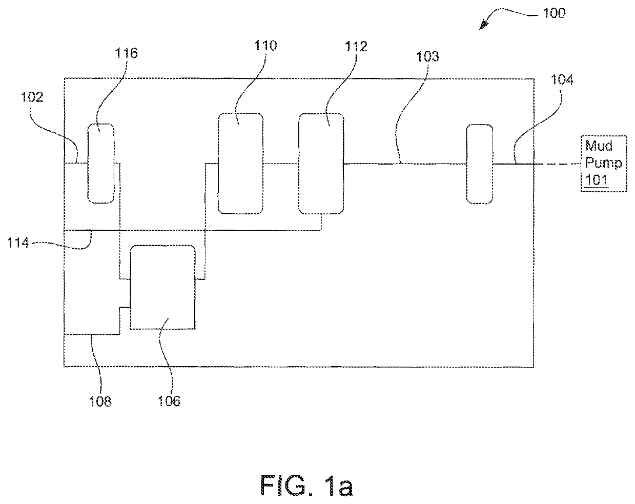
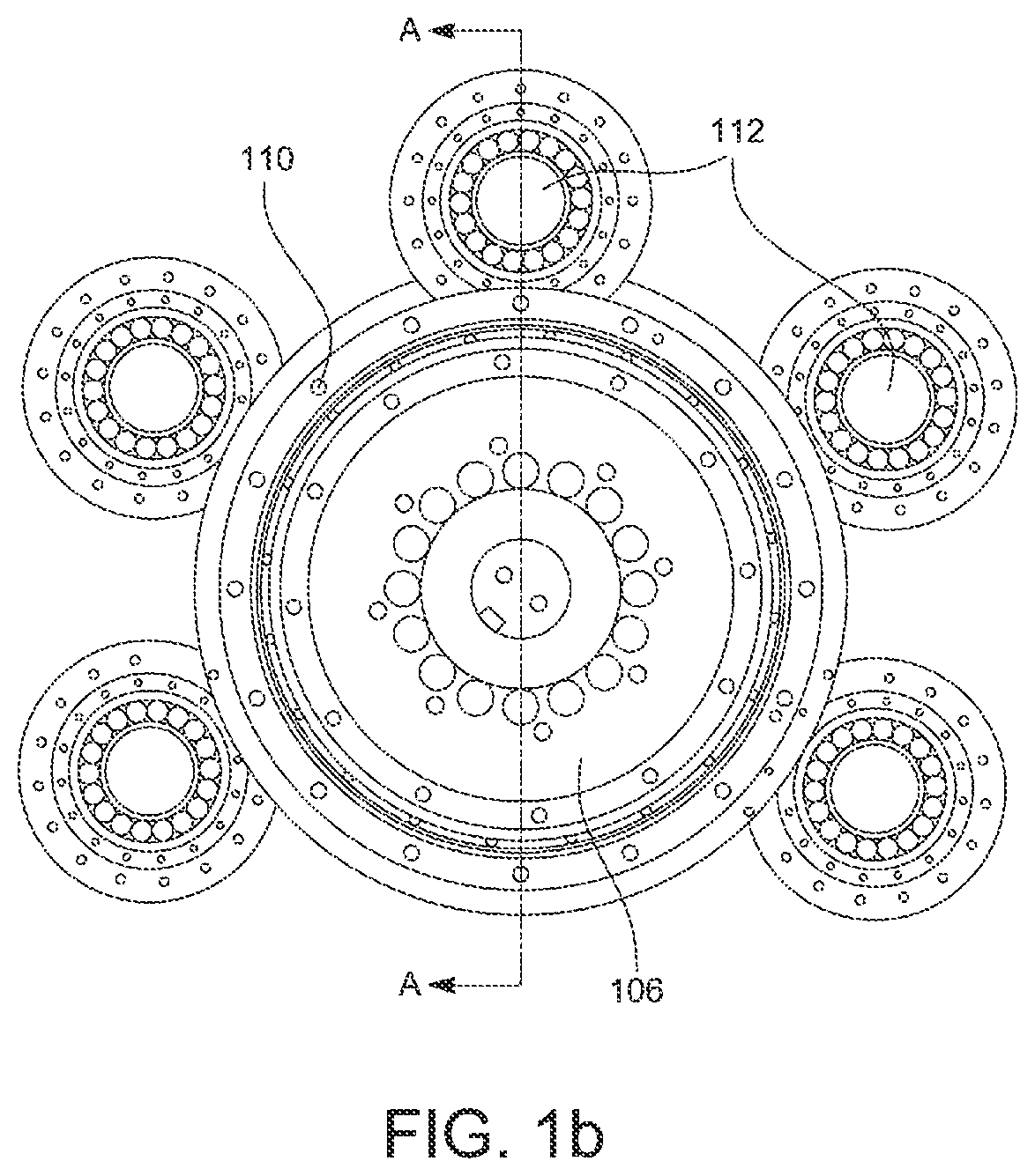
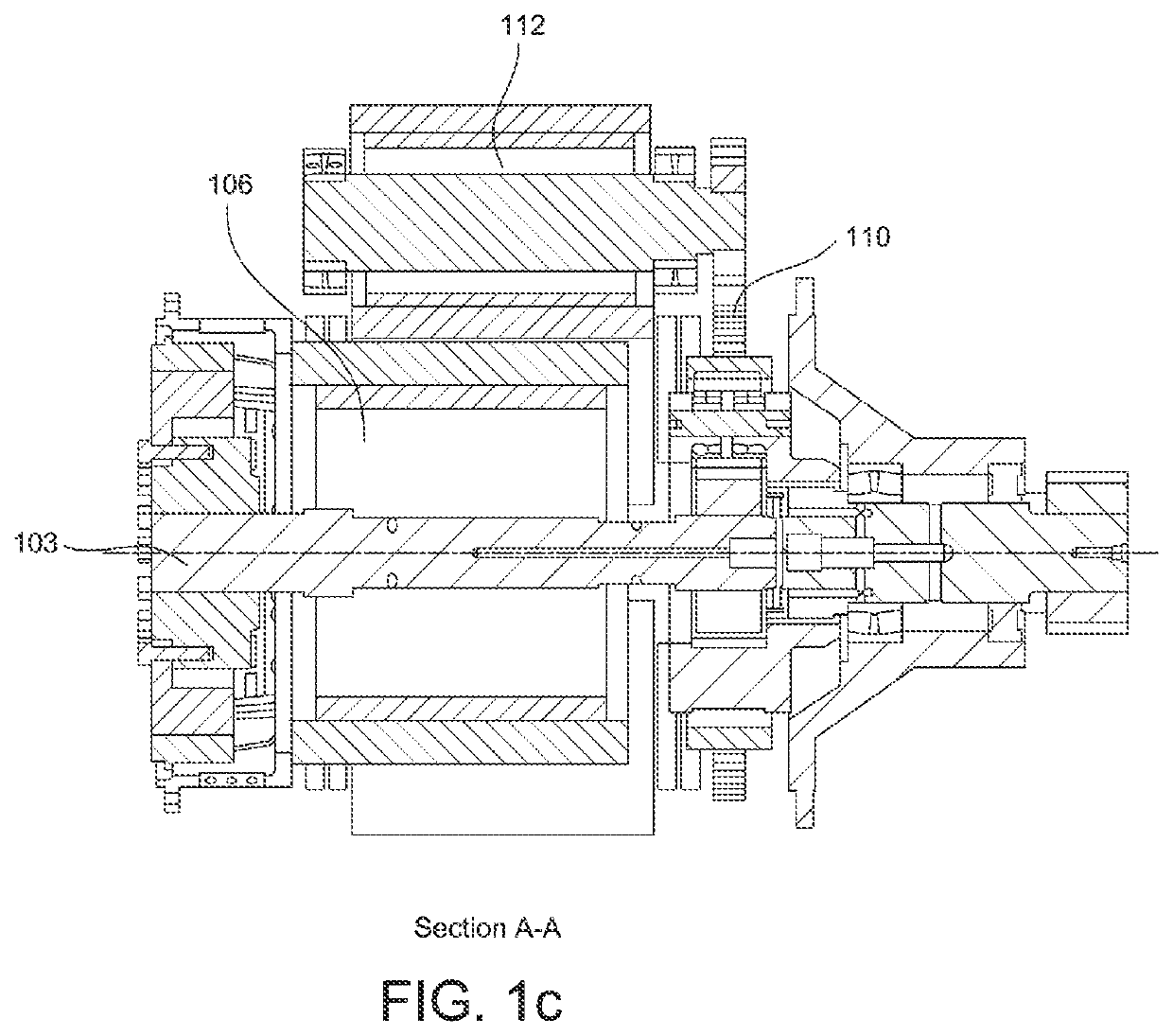
[0025]Referring to FIGS. 1a to 1c, a rig mud pump drive 100 according to a preferred embodiment of the invention is provided. Input power drive shaft 102 connected to an ICE (internal combustion engine) such as, for example, a high-powered diesel engine (not shown) for receiving mechanical input power therefrom. Output power drive shaft 104 is connected via, for example, a shave and belt drive to a rig mud pump 101 for providing mechanical output power thereto. The input power drive shaft 102 and the output power drive shaft 104 is connected via a mechanical drive train 103. Any number of differe...


PUM


Abstract

A power system and method for the adaptive power control of a drilling rig. While operating the internal combustion engine in its efficient operating range, unrequired mechanical power is converted to electrical power for storage, or use via the electrical bus on the rig. When the internal combustion engine is not required to provide mechanical or electrical power it is deactivated, and then reactivated—electrical storage on the system in the meantime providing electrical power to the bus as required. The power supply and management system could be retroactively fitted to an existing drilling rig by the incorporation of a generator and electrical storage device thereon. The system and method of the present invention allow for the optimized use of combustion-based power on a drilling rig while minimizing environmental emissions from the idle running of the at least one internal combustion engine.

Description

[0001]This application is a National Stage filing of PCT Application No.: PCT / CA / 2018 / 050601, filed May 23, 2018, which claims priority to Canada Application No.: 2967921, filed May 23, 2017, both of which are incorporated herein by reference.FIELD OF THE INVENTION[0002]The present invention relates to power supply systems for drilling rigs, and more particularly to a rig mud pump drive and a power management system and method associated therewith.BACKGROUND OF THE INVENTION[0003]System inefficiencies in the power supply of a drilling rig, for example, for use in oil and gas exploration, result in increased fuel consumption and therefore increased emissions output, either due to power losses in the electrical power distribution of sizeable electrical power over a considerable distance of the rig or due to use of oversized and underutilized mechanical drive systems—in particular the mud pump drive system—that are designed for peak power requirements but are utilized most of the time ...

Claims


Application Information

Patent Timeline
Patent Type & Authority Patents(United States)
IPC IPC(8): E21B41/00E21B4/04E21B15/04
CPCE21B41/0085E21B4/04E21B15/045E21B41/00F04B17/03F04B17/05F02B63/04F02B63/06H02J3/32H02J7/14F04B15/02F02D29/04F02D29/06
Inventor ROUSE, CODIEROUSE, WILLIAM JOHN
Owner ROUSE IND INC
Why Eureka
Try Eureka