Card connector

a card connector and card technology, applied in the direction of coupling contact members, coupling device connections, electrical devices, etc., can solve the problem of increasing troublesome mutual interference issues of terminal sets

Active Publication Date: 2022-09-06
V GENERAL TECH CO LTD
View PDF38 Cites 3 Cited by
  • Summary
  • Abstract
  • Description
  • Claims
  • Application Information

AI Technical Summary

Benefits of technology

[0004]The primary objective of the present invention is to realize advantages of bettering high frequency performance, reducing the capacitive effect, and suppressing electromagnetic radiation interference by providing an arrangement of soldering sections.
[0033]Based on the above structure, the first differential soldering section and the second differential soldering section, the third differential soldering section and the fourth differential soldering section, the fifth differential soldering section and the sixth differential soldering section, the seventh differential soldering section and the eighth differential soldering section, and the ninth differential soldering section and the tenth differential soldering section are arranged side by side in a pairwise form, and the third grounding soldering section is arranged between the first and the second differential soldering sections and the third and fourth differential soldering sections; and the fifth grounding soldering section and the sixth grounding soldering section are arranged between the third and fourth differential soldering sections and the fifth and sixth differential soldering sections; and the ninth grounding transmission conductor is arranged between the seventh and eighth differential soldering sections and the ninth and tenth differential soldering sections, so that capacitive effect can be reduced and thus bettering of the high frequency performance and suppressing of electromagnetic radiation interference can be realized.

Problems solved by technology

As a result, the mutual interference issue of the terminal sets is becoming increasingly troublesome.

Method used


Image

  • Card connector
  • Card connector
  • Card connector

Examples


Embodiment Construction

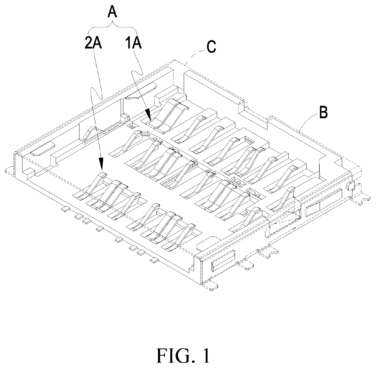
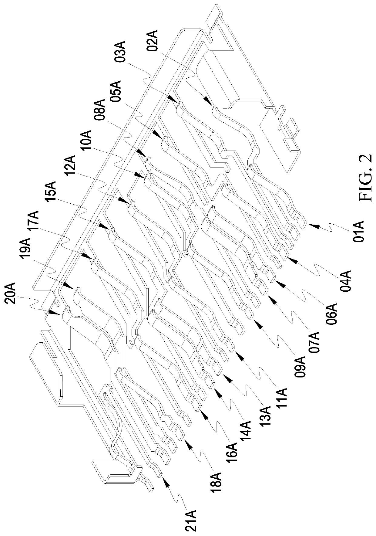
[0046]Referring to FIGS. 1-8, the drawings clearly show the present invention provides a card connector. The card connector comprises a transmission conductor assembly A, an insulative plastic body B arranged outside the transmission conductor assembly A, and a shielding case C arranged outside the insulative plastic body B. The transmission conductor assembly A comprises a first conductor group 1A and a second conductor group 2A;

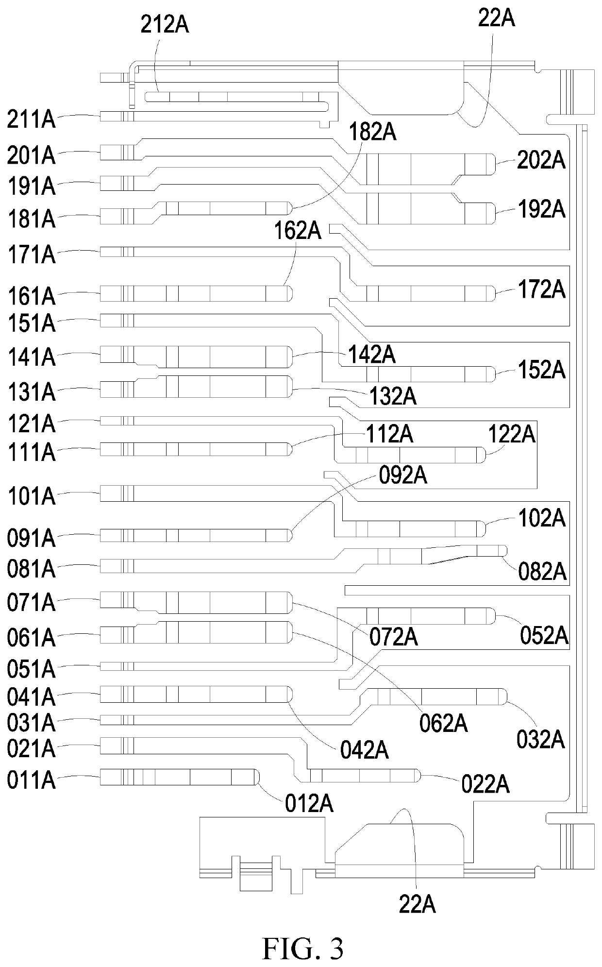
[0047]wherein the first conductor group 1A comprises:

[0048]a backup transmission conductor 01A, wherein the backup transmission conductor 01A has two ends that are extended to respectively form a backup soldering section 011A and a backup spring section 012A;

[0049]a first signal transmission conductor 02A, wherein the first signal transmission conductor 02A has two ends that are extended to respectively form a first signal soldering section 021A and a first signal spring section 022A, and the first signal soldering section 021A is located at one side of the...


PUM


Abstract

A card connector includes a transmission conductor assembly. The transmission conductor assembly includes a first conductor group and a second conductor group. The first conductor group includes a backup transmission conductor, first and second signal transmission conductors, an inspection signal transmission conductor, first to seventh grounding transmission conductors, a command reset transmission conductor, first to sixth differential transmission conductors, first and second power transmission conductors, and a write-protection transmission conductor, each of which has two ends respectively forming a spring section and a soldering section. The second conductor group includes eighth to tenth grounding transmission conductors, seventh to tenth differential transmission conductors, and a third power transmission conductor each of which has two ends respectively forming a spring section and a soldering section. The soldering sections, being so arranged, achieve advantages of bettering high frequency performance, reducing capacitive effect, and suppressing electromagnetic radiation interference.

Description

TECHNICAL FIELD OF THE INVENTION[0001]The present invention relates to a card connector, and more particularly to a card connector featuring bettered high frequency performance, reduced capacitive effect, and suppressed electromagnetic radiation interference.DESCRIPTION OF THE PRIOR ART[0002]Security Digital, commonly abbreviated as SD, refers to a memory card, which is widely used in portable devices, such as digital cameras, personal digital assistants (PDAs), and multimedia players. SD technology is based on the MultiMediaCard (MMC) format. The SD card has a relatively high data transmission rate and is constantly updating the standards thereof. Most of the SD cards are provided with, on a lateral side thereof, with write protection control to prevent accidental data writing in the card. Some of the SD cards even support digital copyright management technology. The size of the SD cards is relatively small and consequently, multiple terminal sets must be included in an SD receptac...

Claims


Application Information

Patent Timeline
Patent Type & Authority Patents(United States)
IPC IPC(8): H01R12/71H01R13/02H01R12/57H01R12/70H01R13/6581H01R107/00
CPCH01R12/716H01R12/57H01R12/7088H01R13/02H01R13/6581H01R2107/00
Inventor YEH, PO-WENCHUNG, HSUAN HOLIN, YUNG-CHANGLIN, YU HUNGYEH, TZU-WEIYEH, YU-LUN
Owner V GENERAL TECH CO LTD
Why Eureka
Try Eureka