Successive maximum error reduction

a maximum error and reduction technology, applied in the field of process plants, can solve problems such as reducing operator confusion, plant abnormal situation, and halting or stalling of sequence programs, and achieve the effect of increasing the accuracy of the mset and reducing operator confusion

Active Publication Date: 2022-09-20
EMERSON PROCESS MANAGEMENT POWER & WATER SOLUTIONS
View PDF6 Cites 0 Cited by
  • Summary
  • Abstract
  • Description
  • Claims
  • Application Information

AI Technical Summary

Benefits of technology

[0023]The improved training technique allows the operator to specify an RMS error threshold value for each process variable. The operator may, for example, specify that the dominant variable has the largest RMS error threshold of all process variables. The improved training technique generates a system matr

Problems solved by technology

At times, however, the plant may experience an abnormal situation where, for example, one of the expected feedback signals related to the permissives, for example, does not occur in the manner expected.
This situation may result in the sequence program halting or stalling.
Importantly, a sequence stall can result in the halt of equipment, which can result in manufacturing delays, lost production or revenue, higher operating costs and possibly even equipment damage.
In a traditional control system however, the operator may not be aware of an impending abnormal situation, and the resulting sequence stall, until the situation actually occurs and the sequence is halted.
A primary contributor to operator unawareness, and thus the development of sequence-stalling events, is the sheer complexity of the systems involved in process control.
However, such monitoring techniques are not complete because the techniques ignore correlations that exist between and among the various parameters of the system.
Unfortunately, power plants and other environments implementing process control systems are generally not a set of small closed systems where each pair of process variables only impact one another.
As a result, creating a set of one-to-one relationships for process variables, similar to that illustrated in the fictional system above (e.g., pressure-to-temperature), may not adequately describe the correlations between and among the process variables.
Often, the process control system issues parameter-specific alarms if any of the parameters violates these predefined limits.
Thus, movement of one significant process parameter without corresponding changes in other process parameters can be a precursor

Method used


Image

  • Successive maximum error reduction
  • Successive maximum error reduction
  • Successive maximum error reduction

Examples


Embodiment Construction

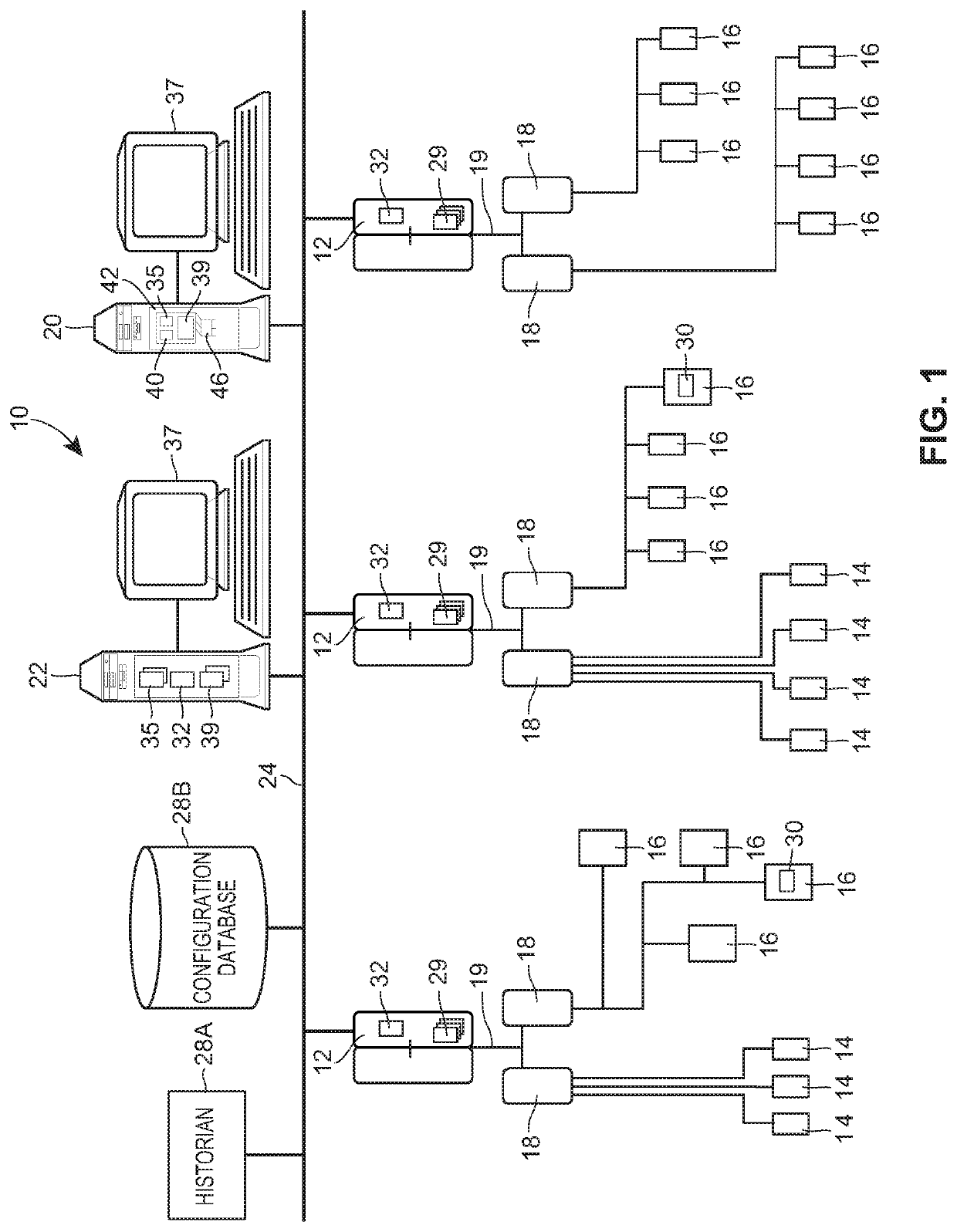
[0030]FIG. 1 illustrates a process plant 10 having an example control network, such as that associated with a power generation plant, in which the improved training technique may be implemented. In particular, process plant 10 of FIG. 1 includes a distributed process control system, having one or more controllers 12, each of which is connected to one or more field devices 14 and 16 via a bus 19 and input / output (I / O) devices or cards 18 which may be, for example, Fieldbus interfaces, Profibus interfaces, HART interfaces, standard 4-20 ma interfaces, etc. The bus 19 can be any type of communication media such as a serial bus, a wireless bus or connection, or the I / O cards 18 can be located physically at the process controllers 12 or can be located remotely. The controllers 12 are also coupled to one or more host or operator workstations 20 and 22 via a data highway 24 which may be, for example, an Ethernet link. Databases 28A and 28B may be connected to the data highway 24 and operat...


PUM


Abstract

A real-time control system includes a fault detection training technique to implement a data-driven fault detection function that provides an operator with information that enables a higher level of situational awareness of the current and likely future operating conditions of the process plant. The fault detection training technique enables an operator to recognize when a process plant component is behaving abnormally to potentially take action, in a current time step, to alleviate the underlying cause of the problem, thus reducing the likelihood of or preventing a stall of the process control system or a failure of the process plant component.

Description

TECHNICAL FIELD[0001]The present invention relates generally to process plants such as power generation and industrial manufacturing plants and, more particularly, to a fault detection training system that performs highly accurate, robust fault parameter optimization to detect faults within the operation of the process plant.DESCRIPTION OF THE RELATED ART[0002]Distributed process control systems, like those typically used in power generation, chemical manufacturing, petroleum processing or other process plants, typically include one or more process controllers communicatively coupled to one or more field devices via analog, digital or combined analog / digital buses. The field devices, which may be, for example, valves, valve positioners, switches, transmitters (e.g., temperature, pressure, level and flow rate sensors), burners, etc. are located within the process environment and perform process functions such as opening or closing valves, measuring process parameters, etc. in respons...

Claims


Application Information

Patent Timeline
IPC IPC(8): G05B23/02G06V30/194
CPCG05B23/0208G05B23/0235G06V30/194G05B23/024Y02P90/02
Inventor CHENG, XU
Owner EMERSON PROCESS MANAGEMENT POWER & WATER SOLUTIONS
Why Eureka
Try Eureka