
Method and apparatus for curing a composite article

a composite article and curing technology, applied in the field of methods and heated tools for curing articles, can solve the problems of adversely affecting the final structural performance of the composite article, high capital expenditure, and high operating costs

Active Publication Date: 2022-09-27
SPIRIT AEROSYST EURO LTD
View PDF8 Cites 0 Cited by
  • Summary
  • Abstract
  • Description
  • Claims
  • Application Information

AI Technical Summary

Benefits of technology

The patent describes a method for heating a composite article to a specific temperature for a set amount of time to ensure complete curing. This method uses functionalised heat output data, which helps accurately determine the curing completion time. By only evaluating the heat output for a small portion of the standard curing cycle, the method saves time. The composite article is then cooled by reducing the heat source output.

Problems solved by technology

Whilst this method of curing is effective, it is associated with high capital expenditure, and high operating costs.
The initial and operating costs for OOA manufacture are significantly reduced, but problems can be encountered in controlling the curing reaction; in terms of ensuring complete curing throughout large items and / or preventing localised overheating, which can adversely affect the final structural performance of a composite article.
However, during manufacture, curing cannot be effectively monitored.
This adds to manufacturing time and energy consumption.
However, this adds to the cost and complexity of manufacture, and for many applications it is not desirable for the thermocouple / thermistors to be present in the final composite article.
However, this signature was seen in tests conducted using a single node on a sample of bulk resin, and the principle was not tested on a composite material in a curing tool, where the signal would be far lower.

Method used


Image

  • Method and apparatus for curing a composite article
  • Method and apparatus for curing a composite article
  • Method and apparatus for curing a composite article

Examples


Embodiment Construction

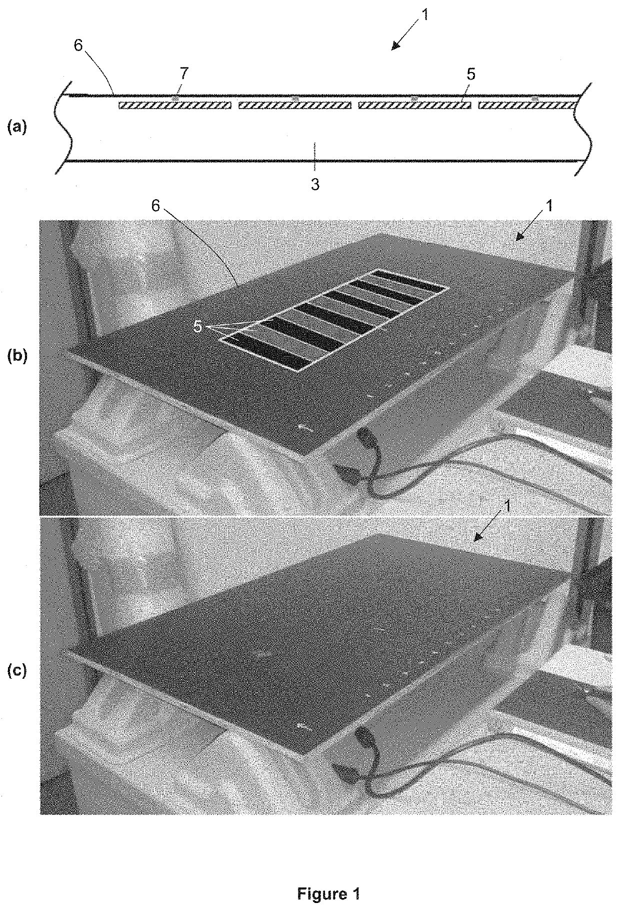
[0119]A one-sided test tool was used to obtain data on curing of test composite articles, to demonstrate the principles of the invention.

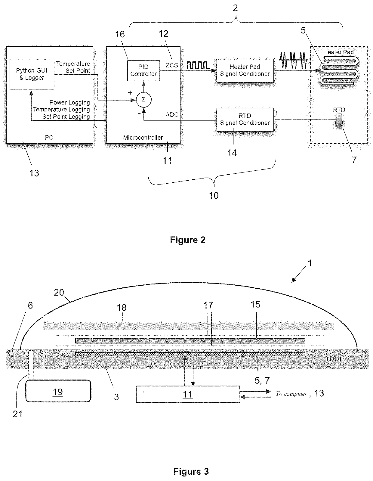
[0120]A test curing tool is shown in FIG. 1(a)-(c). The tool 1 is formed of a glass fibre plate 3 (a mould), to act as a mould for curing a test composite article, with heat sources in the form of eleven embedded silicon heater pads 5 (an example of a heat source) and eleven corresponding thin film PT100 resistive temperature sensors 7 (also referred to as resistive temperature detectors, RTDs).

[0121]As shown in the schematic cross sectional view of FIG. 1(a), the heater pads 5 and the RTDs 7 are located close to the mould surface 6 of the plate 3. The RTDs 7 are centred above each heater pad 5 to facilitate regulation of the heat output of the respective pad. The selected RTDs provide an accurate and repeatable resistance signal that can be related to temperature (i.e. resistance of the RTD 7 being a temperature-related property) within the target...


PUM

PropertyMeasurementUnit
temperatureaaaaaaaaaa
thickaaaaaaaaaa
thickaaaaaaaaaa

Abstract

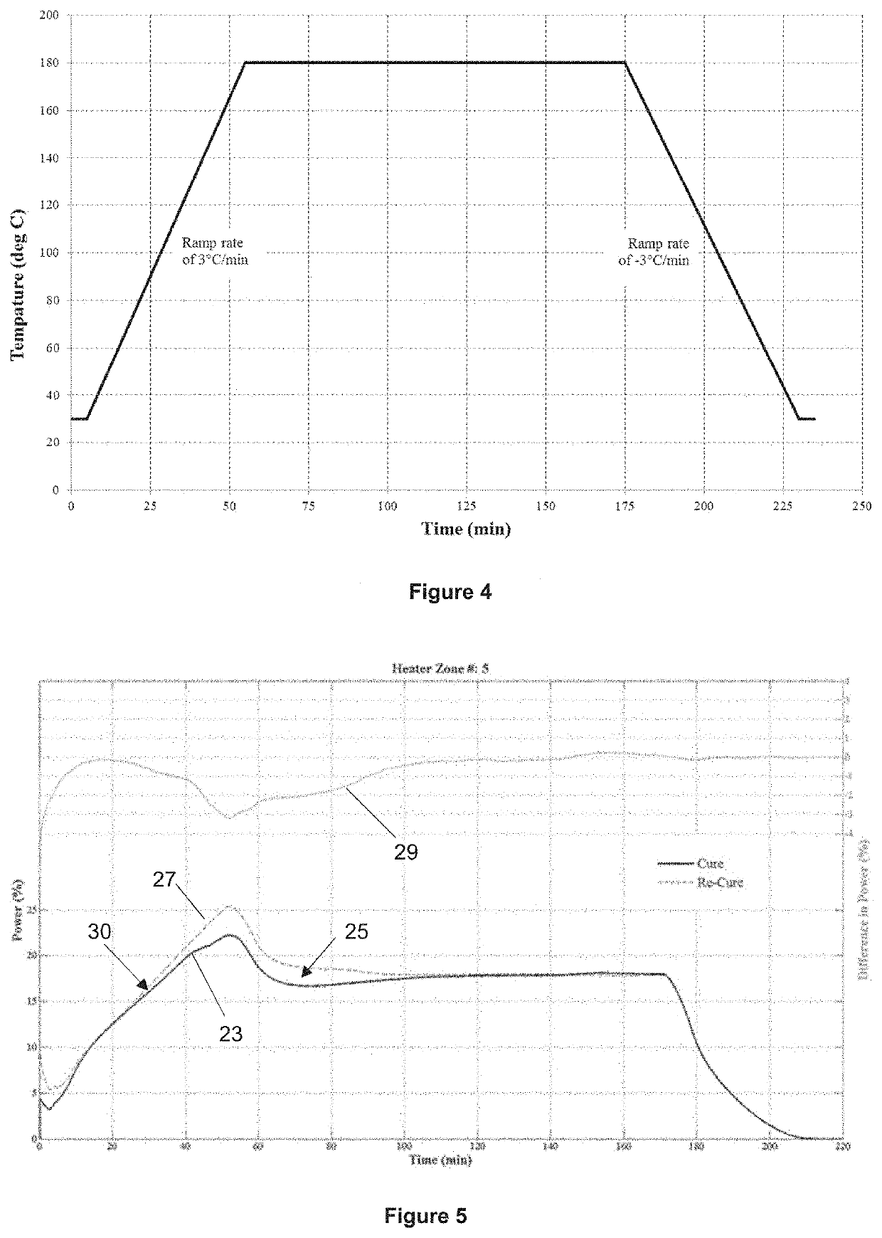
Disclosed is a method of curing a composite article and associated curing apparatus. A heat source is provided for heating the composite article. A temperature related property is detected proximal to the heat source and the heat output is regulated to a predetermined temperature vs. time profile. Heat output vs time data is acquired and functionalised and the curing completion time is determined based on the functionalised heat output vs time data.The method provides for heating a composite article so as to follow a predetermined temperature vs. time profile (i.e. a cure profile) and avoid excessively high temperatures. The required heat output vs time has also been found to be broadly reproducible, and the curing completion time can be more readily determined from functionalised heat output vs time data, for example by identifying reproducible characteristics of the functionalised data.

Description

FIELD OF THE INVENTION[0001]The invention relates to methods and heated tools for curing articles formed from composite materials such as carbon fibre, in particular for aerospace applications.BACKGROUND TO THE INVENTION[0002]Composite materials are widely used in a number of industries, such as aerospace, automotive, civil engineering and sports goods, due to their high strength-to-weight ratio.[0003]Carbon fibre composite material (also known as carbon fibre reinforced polymer, or simply “carbon fibre”), is an example of a composite material formed from a fabric or fibrous component reinforced by a polymeric or resin component.[0004]Carbon fibre composite material is formed from layered carbon fibre fabric impregnated with and reinforcing a polymer matrix. The fabric is formed by carbonizing a synthetic polymer fabric material and may be provided in woven, non-woven or may consist of unidirectional fibres. The carbon fibre fabric provides the majority of the composite material's s...

Claims


Application Information

Patent Timeline
Patent Type & Authority Patents(United States)
IPC IPC(8): B29C35/02B29C70/54C08J5/24B29K63/00B29K105/08B29K307/04
CPCB29C35/0288B29C35/0272B29C70/54B29K2063/00B29K2105/0845B29K2307/04C08J5/24
Inventor HAMILTON, ANDREW W.TACHTATZIS, CHRISTOS
Owner SPIRIT AEROSYST EURO LTD
Learn More