Method for operating a firing furnace, in particular for the dental sector, and firing furnace

a firing furnace and dental technology, applied in the field of firing furnace operation, to achieve the effect of uniform quality

Active Publication Date: 2008-04-24
IVOCLAR VIVADENT AG
View PDF17 Cites 10 Cited by
  • Summary
  • Abstract
  • Description
  • Claims
  • Application Information

AI Technical Summary

Benefits of technology

[0013]The object of the invention is to make available a method for operating a firing furnace, in particular for dental ceramics, which is improved in terms o

Problems solved by technology

However, this method does not take account of different error parameter

Method used


Image

  • Method for operating a firing furnace, in particular for the dental sector, and firing furnace
  • Method for operating a firing furnace, in particular for the dental sector, and firing furnace

Examples


Embodiment Construction

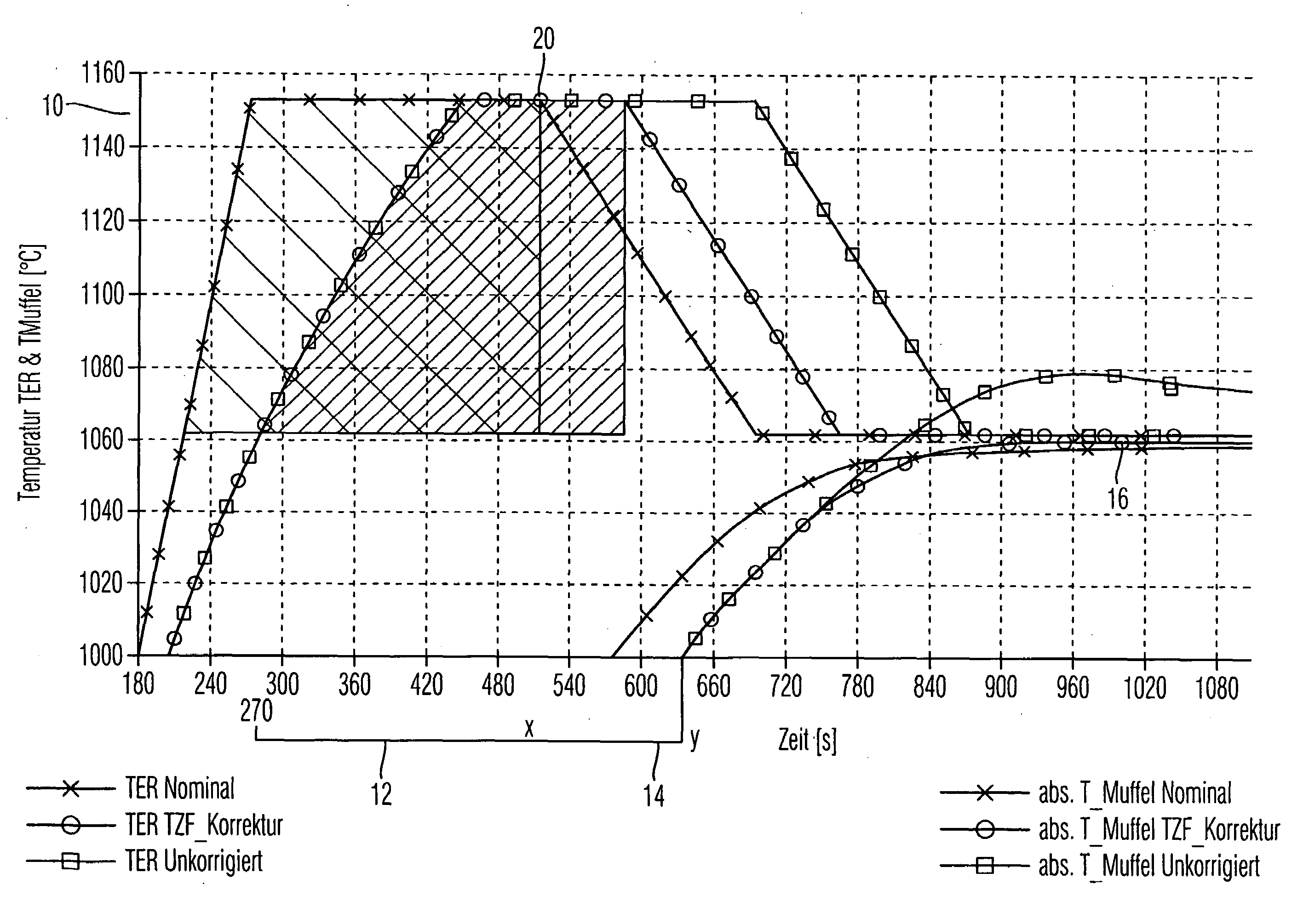
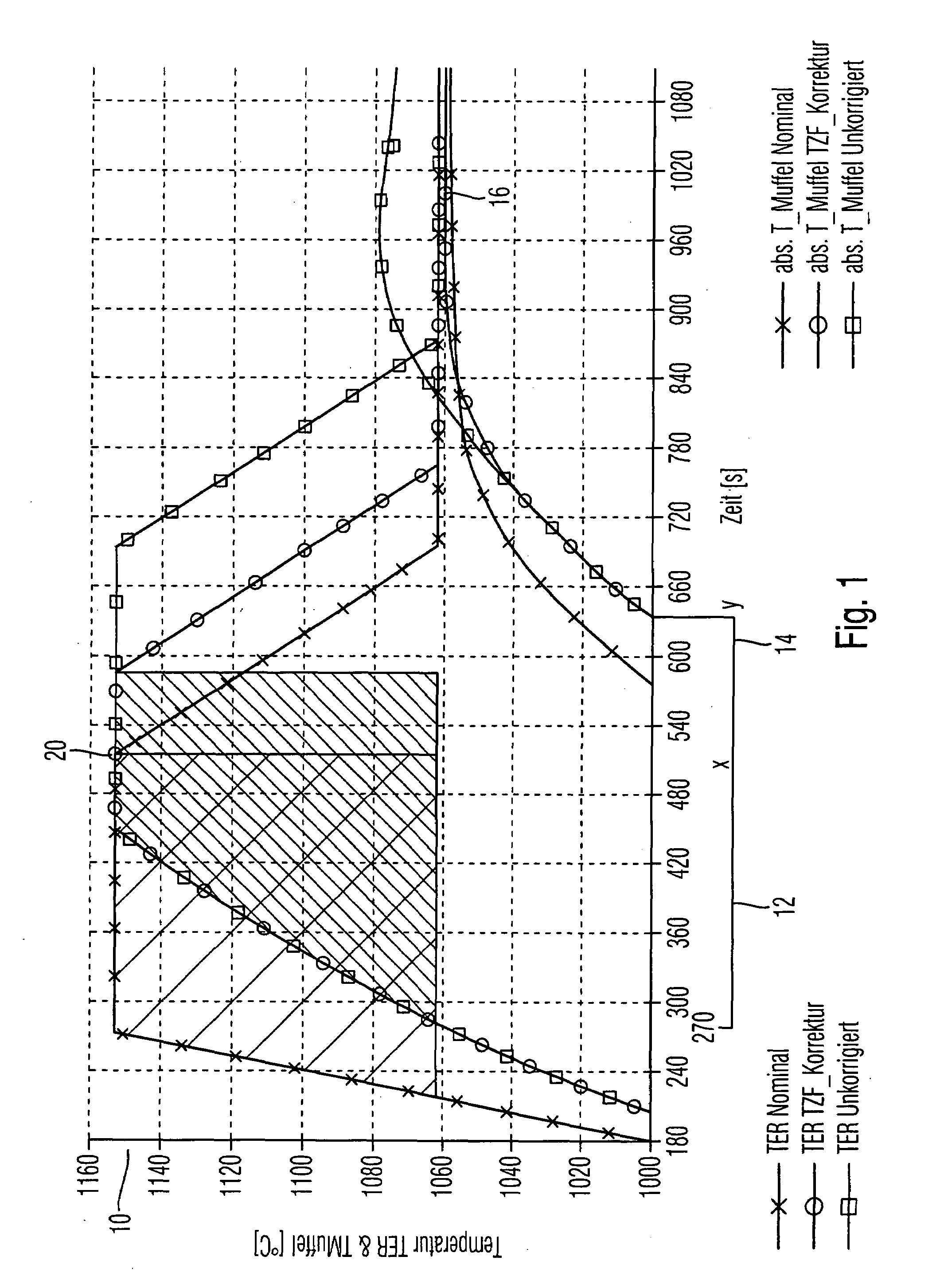
[0036]The temperature is plotted over time in FIG. 1, specifically during a heating period of the firing cycle of a firing furnace according to the invention in one embodiment. In the left-hand area of FIG. 1, the furnace temperature is shown in different temperature profiles, designated by TER, while the right-hand area shows the muffle temperature that was determined via a test muffle. This is designated by T_muffle.

[0037]A muffle is typically brought to a temperature of 800° C. or 850° C., for example, in a preheating furnace. When it is removed from the preheating furnace in order to be introduced into the firing furnace, the temperature typically drops, specifically in most cases by several tens of degrees, and a smaller muffle shows greater cooling than larger muffles. The start temperature in the firing furnace for the muffle in question is accordingly typically lower for a smaller muffle and higher for a larger muffle. However, the smaller muffle automatically heats up more,...


PUM


Abstract

The invention relates to a method for operating a firing furnace, in particular for the dental sector, in which the temperature is measured and, based on the measured temperature, a temperature control is performed. If appropriate, the temperature integral, recorded at discrete points, is determined over the course of time and in particular stored, and is used, if appropriate in addition to the temperature, for controlling the firing furnace.

Description

CROSS-REFERENCE TO RELATED APPLICATIONS[0001]This application claims foreign priority benefits under 35 U.S.C. §119(a)-(d) from German patent application ser. no. 10 2006 049 848.8 filed Oct. 23, 2006.TECHNICAL FIELD[0002]The present invention relates to a method for operating a firing furnace, in particular for the dental sector, and to a corresponding firing furnace in which the temperature in the interior of the is measured and, based on the measured temperature, the temperature in the interior of the furnace is measured and controlled and / or regulated.BACKGROUND OF THE INVENTION[0003]In dental firing furnaces, it is important for the temperature and also the so-called temperature profile, that is to say the course of the temperature over the course of time, to be maintained as precisely as possible, since the quality of the produced dental restoration parts, which can include casts, that is to say metal dental restoration parts, and also sintered parts, depends on this to a grea...

Claims


Application Information

Patent Timeline
IPC IPC(8): A61C13/20F27D19/00F27D21/04
CPCA61C13/20F27D21/00F27D19/00F27B17/025
Inventor JUSSEL, RUDOLF
Owner IVOCLAR VIVADENT AG
Why Eureka
Try Eureka