Micromechanical device and method for manufacturing a micromechanical device

a micromechanical and manufacturing method technology, applied in the direction of fluid pressure measurement, fluid pressure measurement by electric/magnetic elements, instruments, etc., can solve problems such as vibration resistance of the housing

Active Publication Date: 2022-11-01
ROBERT BOSCH GMBH
View PDF18 Cites 2 Cited by
  • Summary
  • Abstract
  • Description
  • Claims
  • Application Information

AI Technical Summary

Problems solved by technology

However, the sensors not only register external pressure fluctuations, but are also sensitive to vibrations of the housing.

Method used


Image

  • Micromechanical device and method for manufacturing a micromechanical device
  • Micromechanical device and method for manufacturing a micromechanical device
  • Micromechanical device and method for manufacturing a micromechanical device

Examples


Embodiment Construction

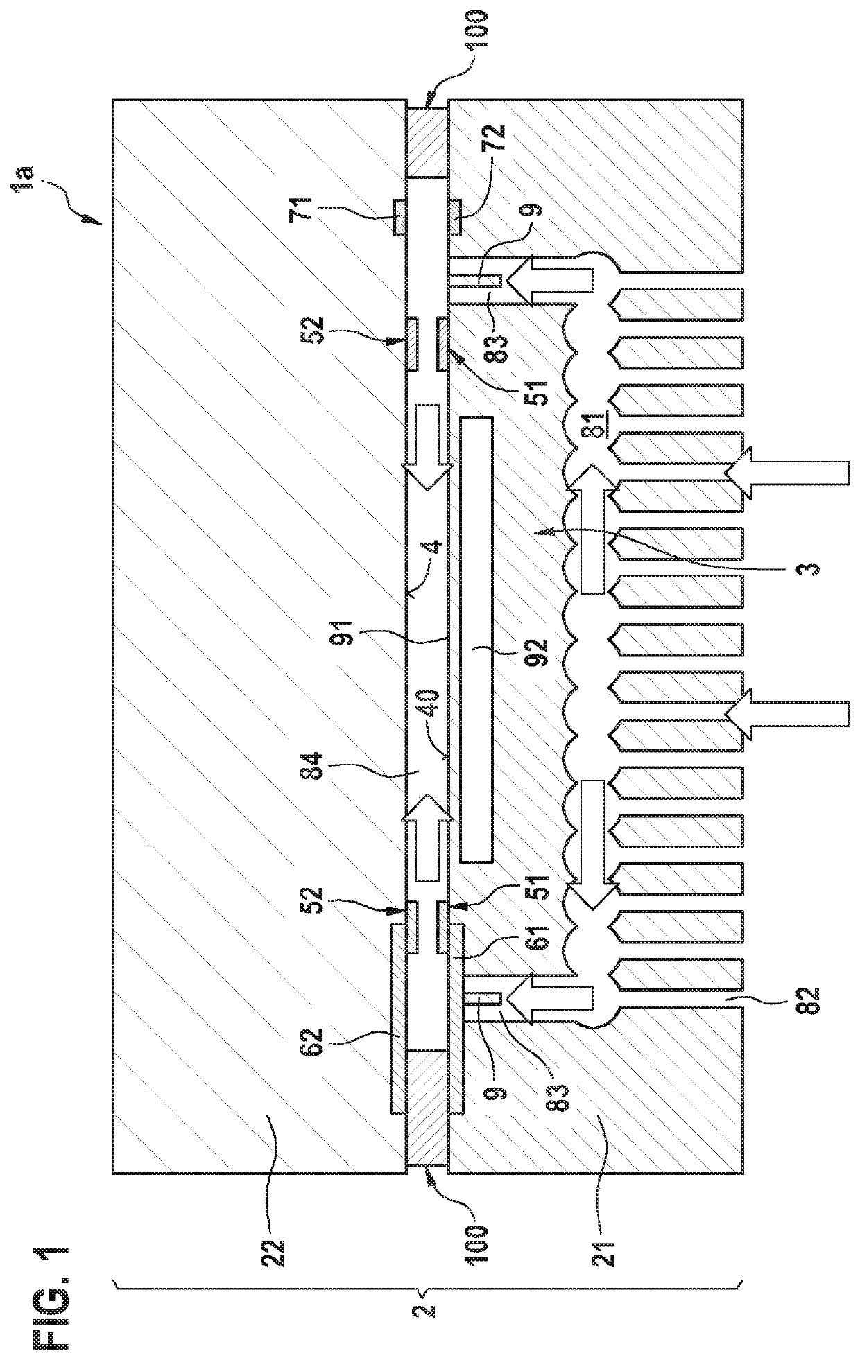
[0024]FIG. 1 shows a schematic cross-sectional view of a micromechanical device 1a according to one specific embodiment of the present invention. Micromechanical device 1a includes a carrier substrate 2 that is made up of a MEMS structure 21 and an integrated circuit or an ASIC 22 that are connected to one another via bond connections 100, using eutectic alloys. A measuring channel 84 extends between MEMS structure 21 and integrated circuit 22.

[0025]MEMS structure 21 includes a sensor device 3 that may be used for measuring a pressure in measuring channel 84. For this purpose, sensor device 3 includes a diaphragm 91 that closes off a cavity 92, formed in a substrate of sensor device 3, in an airtight manner. A reference gas having a reference pressure is situated in cavity 92. Mechanical stresses or changes in the pressure in measuring channel 84 relative to the reference pressure generate deflections or oscillations of diaphragm 91, which may be detected via known measuring element...


PUM

PropertyMeasurementUnit
relative permittivityaaaaaaaaaa
distanceaaaaaaaaaa

Abstract

A micromechanical device that includes a carrier substrate; a sensor device that is situated on the carrier substrate and spaced apart from a surface section of the carrier substrate with the aid of spring elements in such a way that the sensor device is oscillatable relative to the surface section; and at least one stopper element, situated on the sensor device and/or on the surface section of the carrier substrate, which limits a deflection of the sensor device in the direction of the surface section.

Description

FIELD OF THE INVENTION[0001]The present invention relates to a micromechanical device that may be used for measuring a physical variable such as an ambient pressure. Moreover, the present invention relates to a method for manufacturing a micromechanical device.BACKGROUND INFORMATION[0002]Micromechanical pressure sensors are used for ascertaining pressure and mechanical stresses in portable devices, and also in industrial and household apparatuses. One example of a pressure sensor is discussed in German patent document DE 10 2010 031197 A1. However, the sensors not only register external pressure fluctuations, but are also sensitive to vibrations of the housing. However, it is often desirable to eliminate or at least reduce the effect of these vibrations.SUMMARY OF THE INVENTION[0003]The present invention provides a micromechanical device having the features described herein, and a method for manufacturing a micromechanical device having the features described herein.[0004]Accordingl...

Claims


Application Information

Patent Timeline
Patent Type & Authority Patents(United States)
IPC IPC(8): G01L19/06B81B3/00G01L9/00B81B7/00G01R27/26G01L19/14G01N27/12G01N33/18G01N27/04G01N27/22
CPCG01L9/0073B81B3/0051B81B7/0016G01L19/0618G01L19/0654G01L19/146G01R27/2605B81B2201/0264B81B2203/0163G01N27/048G01N27/223G01N2291/02845
Inventor HEUCK, FRIEDJOFSCHWARZ, MIKEFRIEDRICH, THOMASSENZ, VOLKMAR
Owner ROBERT BOSCH GMBH
Why Eureka
Try Eureka