Supercharge Your Innovation With Domain-Expert AI Agents!

Systems and methods for modulation control of a camera filter device

a filter device and modulation control technology, applied in the direction of instruments, magnitude/direction of magnetic fields, optics, etc., can solve the problems of inability to retrieve information, state of the art cameras cannot record the true signal path of light intensity, and fluctuation of the brightness of light sources within the scen

Active Publication Date: 2022-11-15
SMR PATENTS S A R L
View PDF5 Cites 0 Cited by
  • Summary
  • Abstract
  • Description
  • Claims
  • Application Information

AI Technical Summary

Benefits of technology

The patent describes a method to prevent flickering in streamed video images by setting the exposure time and using an electro- or magneto-optic modulator to dynamically control the amount of light in the image. This method allows for improved image quality and prevents information loss during exposure. Additionally, the method is flexible, works at different temperatures, and contains no moving parts, making it superior to other solutions. The method can be used with various video capture devices and is effective in reducing flickering in high-speed video imaging.

Problems solved by technology

However, due to a relatively long exposure time an overexposure of the image acquisitions 15a to 15c is put up with.
State of the art cameras are incapable of recording the true signal path of the light intensity as they have a relatively small frame rate and therewith under sample said signal.
Furthermore, if the exposure time is much shorter than the time between two frames, there are large gaps, where no information is retrieved.
In videos this often leads to a fluctuating brightness of the light sources within the scene.
These fluctuations—referred to as ‘flicker’—can be disturbing and distracting to both the human observer and machine vision systems.
Thus, there is the danger that the information about the average intensity of the light source gets lost.
The known software-based method does not address the cause of flicker, but rather attempts to regain lost information about the true behavior of amplitude-modulated lights, that comes along with some time delay.
Additionally, it accepts some misinterpretation during a classification step so that a displayed processed streamed video images might provide a distorted view of a scene.
In addition, as the light source itself needs to be detected, flicker appearing in a scene that is illuminated by an amplitude-modulated light source or light reflections from said light is not sufficiently corrected.
When modulating a laser beam, the beam only goes directly through the center of the Pockels cell and lens errors that impede two-dimensional optical imaging are not relevant for the modulation of a single beam.
For example, crystals like potassium dihydrogenphosphate used for Pockels cells typically have a high optical extinction and therewith large lens errors.
In contrast, known software-based solutions have to rely on incomplete data and therewith can only arbitrarily fill the gaps by altering the image sequences based on assumption, rather than actually recovering the data.

Method used


Image

  • Systems and methods for modulation control of a camera filter device

Examples


Embodiment Construction

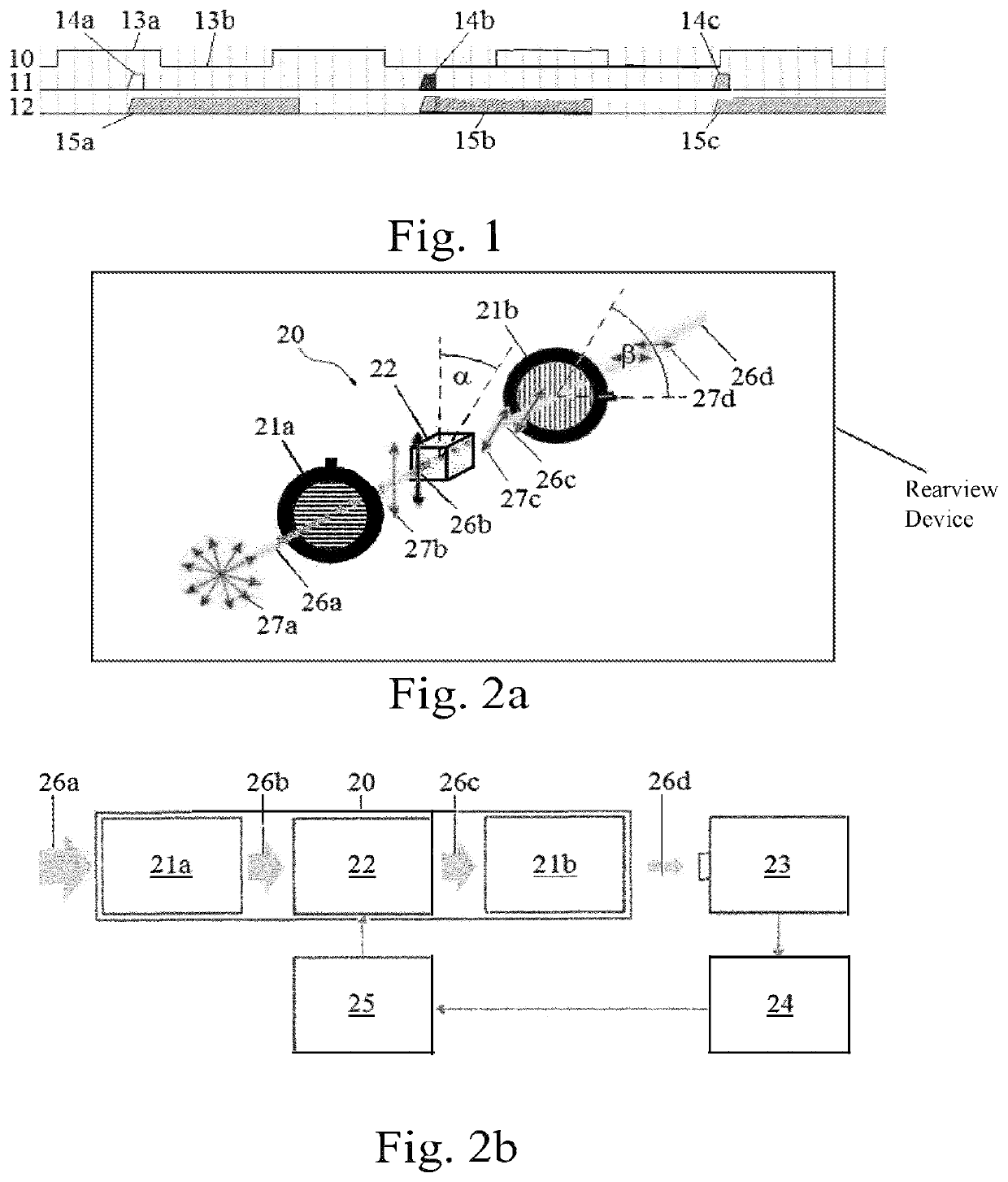
[0062]An electro- or magneto-optic modulated anti-flicker filter device is suited for a camera system, in particular a camera device used within an automotive environment, preferably within a rear view device.

[0063]FIG. 2a shows an embodiment of an electro- or magneto-optic light intensity filter 20 which is suited to prevent overexposure. The intensity filter 20 comprises a first polarizer 21a, an electro- or magneto-optic modulator 22, and a second polarizer 21b. Incoming light 26a from a not shown light source is provided with a uniform mixture of linear polarizations 27a at all possible angles and passes the first polarizer 21a such that it turns into polarized light 26b with a first polarization 27b prior to entering the electro- or magneto-optic modulator 22. By passing the first polarizer 21a the initial intensity of the incoming light 26a is reduced by about half. Depending on the voltage or current applied to the modulator 22 the first polarization 27b of the polarized ligh...


PUM

PropertyMeasurementUnit
frequencyaaaaaaaaaa
frequencyaaaaaaaaaa
exposure timeaaaaaaaaaa

Abstract

A modulation control method for a filter device for avoiding flicker appearing in streamed video images before acquiring images, includes setting the exposure time to be equal or longer than an oscillating light source's period duration or to be as long as possible between two frames in the image acquisition of streamed video images, polarizing of incoming light in a first polarizer to turn into polarized light with a first polarization, altering the polarization of the light with the first polarization in an electro- or magneto-optic modulator by an angle α to turn into light with a second polarization, and reducing an amount of light with the second polarization in a second polarizer.

Description

CROSS-REFERENCE TO RELATED APPLICATIONS[0001]This application is a National Stage Entry of International Patent Application No. PCT / EP2018 / 070461, filed Jul. 27, 2018, which claims the benefit of foreign priority to German Patent Application No. 10 2017 117 765, filed Aug. 4, 2017, each of which is herein incorporated by reference in its entirety for all purposes.BACKGROUND1. Field of the Invention[0002]The present disclosure relates to a modulation control method for a filter device, an electro- or magneto-optic modulated anti-flicker filter device, a camera system with such a filter device, and a rear view device of a motor vehicle with such a camera system.2. Related Art[0003]Flicker of artificial light sources in videos originates from the fact, that these light sources emit light with oscillating luminance. Amongst the affected light sources are street lights, traffic lights and car lights, i.e., lights, that are highly important for motor traffic. These lights appear steady to...

Claims


Application Information

Patent Timeline
Patent Type & Authority Patents(United States)
IPC IPC(8): G02F1/09G01R33/032G02F1/1335H04N23/75
CPCG02F1/09G01R33/032G02F1/133509G02F1/0136H04N23/55H04N23/745H04N23/75H04N23/73
Inventor JOCHMANN, THOMASHERRMANN, ANDREAS
Owner SMR PATENTS S A R L
Features
  • R&D
  • Intellectual Property
  • Life Sciences
  • Materials
  • Tech Scout
  • Unparalleled Data Quality
  • Higher Quality Content
  • 60% Fewer Hallucinations
Learn More