Non-pneumatic wheel comprising a circumferential reinforcement structure

a non-pneumatic and reinforcement structure technology, applied in the direction of spoked wheels, tyre parts, transportation and packaging, etc., can solve the problems of complex construction, high production cost, and maintenance costs, and achieve the effect of improving production efficiency, improving production efficiency and reducing production costs

Active Publication Date: 2022-11-22
MICHELIN & CO CIE GEN DES ESTAB MICHELIN
View PDF18 Cites 0 Cited by
  • Summary
  • Abstract
  • Description
  • Claims
  • Application Information

AI Technical Summary

Benefits of technology

[0006]First of all, a first objective of the invention is to provide a non-pneumatic wheel that offers improved performance.
[0007]Another objective of the invention consists in providing an arrangement of crown reinforcing elements that are able to be shaped in a wide range of variants, thereby making it possible to adapt the characteristics of the crown according to the type of tyre.
[0010]Such an architecture makes it possible to simplify the crown region, to obtain a highly compact reinforcing region while providing significant reductions in weight. The number of radially superposed layers and the respective arrangement thereof makes it possible to optimize the endurance of the crown region. The method of manufacture is simple to implement. Finally, this architecture makes it possible to reduce the rolling resistance on account of the simplified, optimized and thinner arrangement.
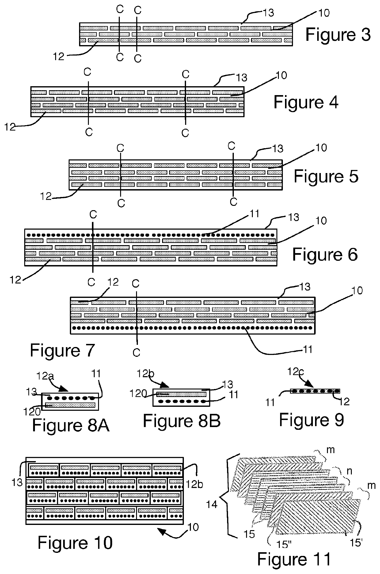
[0011]According to one advantageous embodiment, the annular reinforcing structure comprises N radially superposed layers, N being greater than three, a virtual axis C-C substantially perpendicular to the strips intersects at least N−1 strips in any axial position of the said virtual axis in the annular reinforcing structure. For example, with four radially superposed layers of strips, any perpendicular axis passes through at least three strips. This embodiment provides a crown region that is particularly uniform, thereby making it possible to obtain advantageous dynamic qualities such as, for example, excellent material strength, even under harsh driving conditions, particularly under cornering. With four layers of strips, the strips of each layer of superposed strips radially overlap the strips of the layer of strips that is radially on the inside of it to an extent of at least 20% and at most 80%.

Problems solved by technology

This type of tyre does, however, have a number of disadvantages associated with its structure, such as the complexity, the need for maintenance, and the risks of damage, particularly of puncturing.
This construction is also complex and relatively expensive to produce.

Method used


Image

  • Non-pneumatic wheel comprising a circumferential reinforcement structure
  • Non-pneumatic wheel comprising a circumferential reinforcement structure
  • Non-pneumatic wheel comprising a circumferential reinforcement structure

Examples


first embodiment

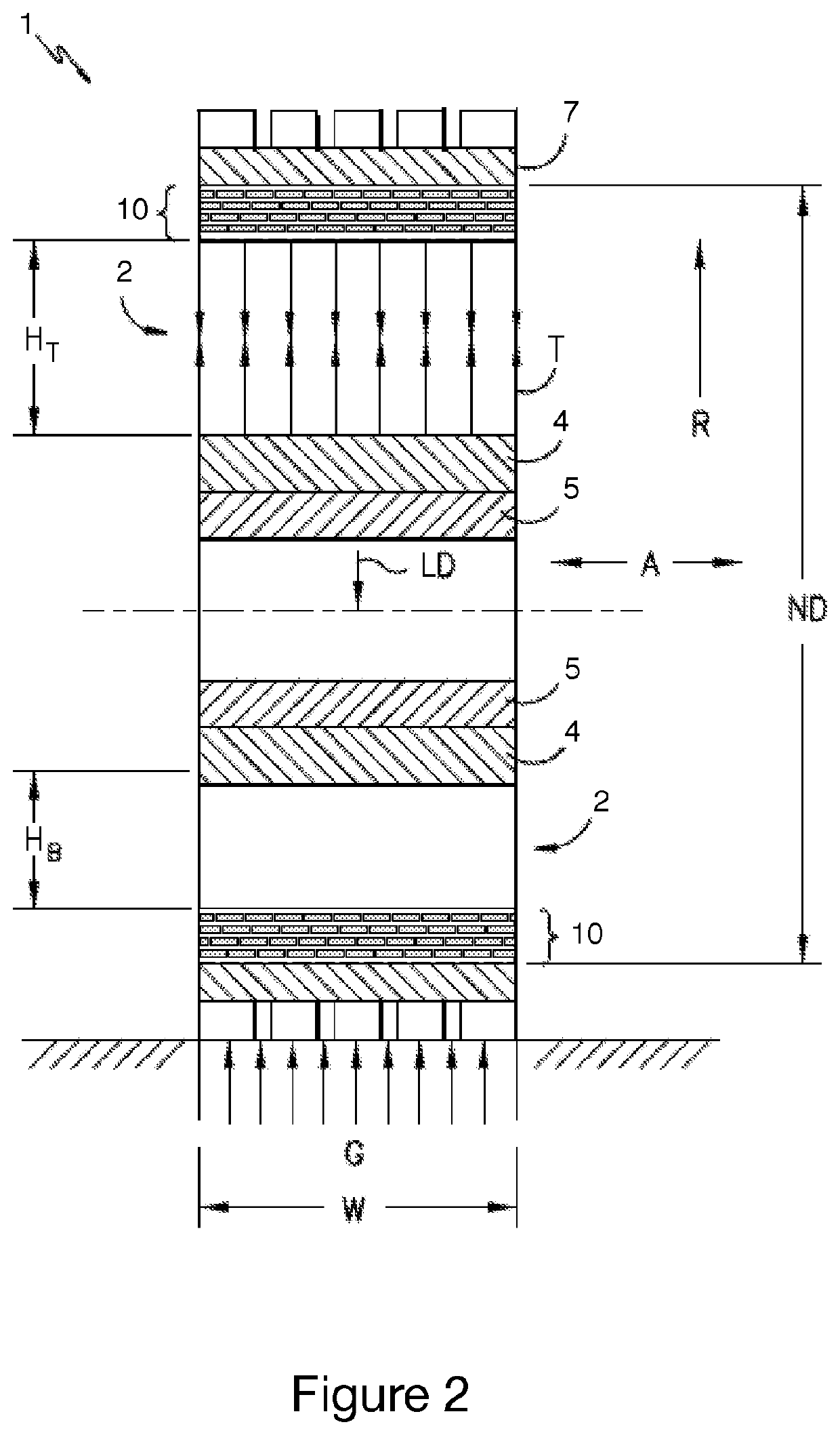
[0058]FIG. 3 illustrates an annular reinforcing structure 10 according to the invention. According to this embodiment, strips 12 made of a thermoplastic film are disposed side by side at an angle substantially in the region of 0 degrees, and more broadly at an angle less than substantially 12 degrees to the circumferential direction. The whole is embedded in a matrix 13 made up of an elastomeric compound, preferably a diene elastomeric compound. The staggered arrangement of the strips is realized for example by first winding-off starting at a given azimuth, and second winding-off starting at 180 degrees. As an alternative, the strips are positioned by first winding-off in one given axial direction, followed by second winding-off in the opposite axial direction.

[0059]The strips of a layer are separated by a region of rubber (or the elastomeric compound) referred to hereinafter as rubber bridge.

[0060]In the exemplary embodiment of FIG. 3, the crown 10 comprises three layers of strips ...

second embodiment

[0073]the strips is presented with reference to FIGS. 8A, 8B and 9. FIG. 8A illustrates an exemplary embodiment in which a thermoplastic film 120 as described hereinabove is surmounted by a layer 11 of reinforcing threads, preferably textile. The whole is embedded in a matrix 13 made up of an elastomeric compound, preferably a diene elastomeric compound, and forms a composite strip 12a. FIG. 8B presents an alternative form of composite strip 12b with a reverse geometry, the layer of threads 11 being arranged radially on the inside with respect to the thermoplastic film 120.

[0074]FIG. 9 illustrates a third example of composite strip 12c in which a layer of reinforcing threads 11 is integrated directly into a thermoplastic film 120. This alternative form has the additional advantages of greater lightness of weight and very high compactness.

[0075]FIG. 10 illustrates one example of a layout comprising four layers of strips, using strips such as those presented with reference to FIG. 8B;...

third embodiment

[0082]the strips 14 is described hereinbelow and illustrated in FIG. 11. The reinforcing strips 14 are made up of a laminate of at least 3 composite layers, each composite layer comprising mutually-parallel oriented high-modulus fibres (15, 15′, 15″) making an angle α with the circumferential direction (which is to say the longitudinal direction of the strip), coated in a polymer matrix. As a preference, the angle α formed by the fibres with the circumferential direction ranges from −90° to 90°.

[0083]Preferentially, the laminate comprises:[0084]n interior composite layers having fibres 15 of which the angle with the circumferential direction is 0°, n being a number greater than or equal to 1, preferably ranging from 1 to 20, more preferably ranging from 1 to 12, more preferably still from 1 to 6, these interior composite layers being juxtaposed with one another and flanked on each side respectively by m exterior composite layers,[0085]each exterior composite layer having fibres 15′,...


PUM

PropertyMeasurementUnit
angleaaaaaaaaaa
angleaaaaaaaaaa
angleaaaaaaaaaa

Abstract

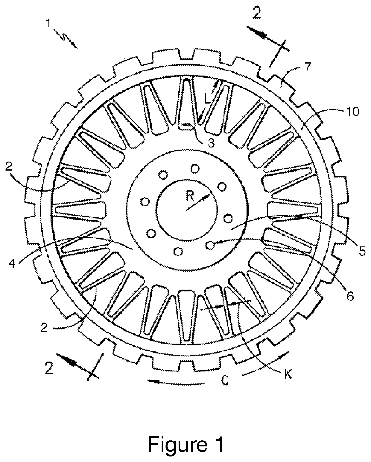
A non-pneumatic wheel (1) comprises a crown reinforcing region (10) itself radially on the inside of a tread (7), the crown reinforcing region (10) comprising a plurality of reinforcing strips (12, 14) arranged in at least three layers of strips (12, 14) arranged in such a way that a virtual axis C-C substantially perpendicular to the strips intersects at least two strips in any axial position of the virtual axis in the crown reinforcing region.

Description

TECHNICAL FIELD OF THE INVENTION[0001]The present invention relates to reinforcing elements for a non-pneumatic wheel. It relates more particularly to architectural elements for the crown of this wheel.PRIOR ART[0002]A conventional pneumatic tyre, normal operation of which requires it to be inflated, is a well-known solution able to meet strict requirements in terms of comfort, mass, rolling resistance, etc. This type of tyre does, however, have a number of disadvantages associated with its structure, such as the complexity, the need for maintenance, and the risks of damage, particularly of puncturing. In order to alleviate some of these disadvantages, non-pneumatic wheels were developed already several years ago. Examples of non-pneumatic wheels are disclosed in the following documents: U.S. Pat. Nos. 6,769,465, 6,994,134 and 7,013,939 for example. Certain non-pneumatic wheels comprise a peripheral ring, referred to more commonly as a “shear band”, as for example in U.S. Pat. No. 7...

Claims


Application Information

Patent Timeline
Patent Type & Authority Patents(United States)
IPC IPC(8): B60C7/18B60B1/06B60B5/02
CPCB60C7/18B60B1/06B60B5/02B60B2360/341B60B2900/711B60C7/146
Inventor MERINO LOPEZ, JOSEPATAUT, GAELRIGO, SEBASTIEN
Owner MICHELIN & CO CIE GEN DES ESTAB MICHELIN
Why Eureka
Try Eureka