
Strong lightweight panel element and apparatus for manufacturing the same

Inactive Publication Date: 2001-08-09
R S TECHN
View PDF0 Cites 29 Cited by
  • Summary
  • Abstract
  • Description
  • Claims
  • Application Information

AI Technical Summary

Benefits of technology

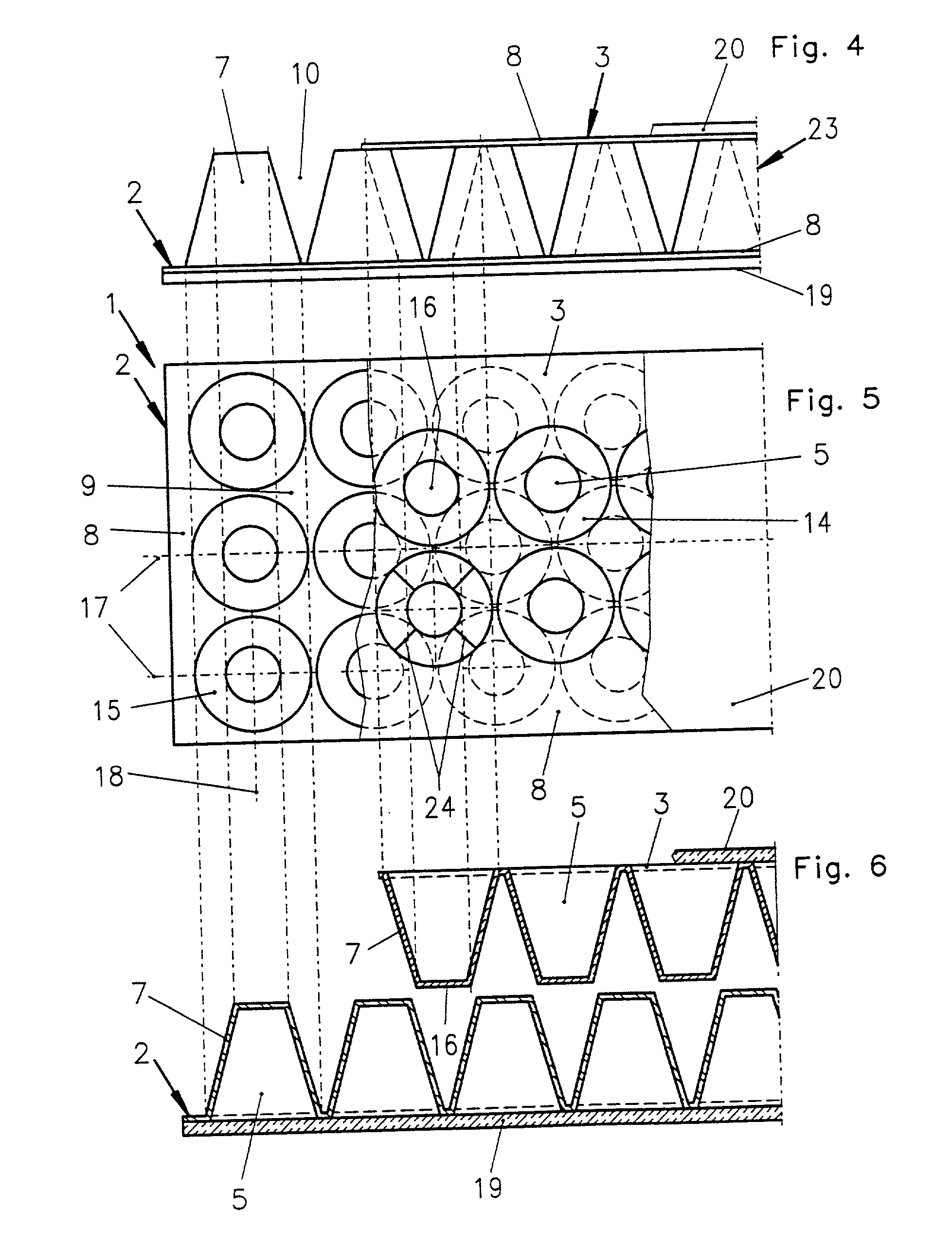
[0009] Due to the intermeshing and interlocking arrangement of the respective cup members of the first layer and of the second layer, there is a strong mechanical connection and bracing achieved between the two respective layers on opposite sides or opposite surfaces of the panel element. The interlocking effect is almost like interlocking gear teeth or the interlocking teeth of a zipper, whereby the first cup members and second cup members are braced against one another in a force transmitting manner. This interlocking or intermeshing is repeated through the uniform intermeshing pattern of the respective cup members in two dimensions, i.e. across the entire width and length of the panel element. Also, the respective layers are thermally fused and bonded to each other along the significantly increased surface area of overlapping contact surfaces of the intermeshing cup members. This effect significantly increases the strength and bending stiffness of the finished panel element to a surprising degree.
[0010] Moreover, due to the variable intermeshing that can be achieved with the tapering configuration of the cup members, and depending on the particular chosen shape of the cup members, the panel element is not limited to a flat planar configuration, but rather may be formed or molded into three dimensional contours as needed for any particular application. Namely, the arrangement of the cup members allows for differing degrees of intermeshing of the respective cup members into the tapering spaces of the opposite facing layer of cup members, and also allows flexing and forming of the respective cup member layer during the fabrication process. While the panel element is being fabricated, under the influence of heat and molding pressure, the materials of the panel element remain deformable and yielding, so that each respective cup member yields or deforms to a varying degree depending on the molding needs at that particular location.
[0012] On the one hand, this provides an excellent opportunity for incorporating and thereby disposing of otherwise unusable mixed scrap material. On the other hand, the material may be selected from among any available materials at the time of manufacturing the respective panel element, so as to achieve the required degree of noise damping, thermal insulation, and mechanical strengthening. In other words, essentially any type of material or mixed material can be filled into the cup chambers, as long as it provides the required noise damping (and other) characteristics. Thus, it is not necessary to always continuously provide the same filler material when manufacturing a series production of the panel element.
[0013] Furthermore, the filler material that substantially fills out the interior space or chamber within each cup member serves to mechanically support and brace the cup walls of the respective cup member. In this manner, a crushing or collapsing of the cup members is prevented, which further contributes to the strength and stiffness of the finished panel, as well as the moldability or formability thereof during the manufacturing process.

Problems solved by technology

While such honeycomb core panels are available, made of many different material combinations, for many different applications, they generally suffer certain common disadvantages.
For example, such honeycomb panels are conventionally limited to flat planar panel elements, i.e. they cannot be formed or molded to three dimensionally contoured shapes as required for special applications.
This is due to the limitations of the honeycomb core, and the manner in which it is manufactured.
If the bond between the cover skins and the honeycomb core fails, delamination of the panel is a serious risk.
The recycling of previous scrap material, often including a mixture of various thermoplastic materials, thermoset materials, natural materials such as wood fibers, plant fibers, fabrics, leather, and the like, is generally associated with a high cost, if the materials need to be separated, and then separately reprocessed.
In view of such costs for separately processing materials, a huge volume of mixed recycled or scrapped materials of almost undefinable content is constantly available in the motor vehicle manufacturing industry, and is generally being disposed of in various ways, which are no longer environmentally acceptable.

Method used


Image

  • Strong lightweight panel element and apparatus for manufacturing the same
  • Strong lightweight panel element and apparatus for manufacturing the same
  • Strong lightweight panel element and apparatus for manufacturing the same

Examples


Embodiment Construction

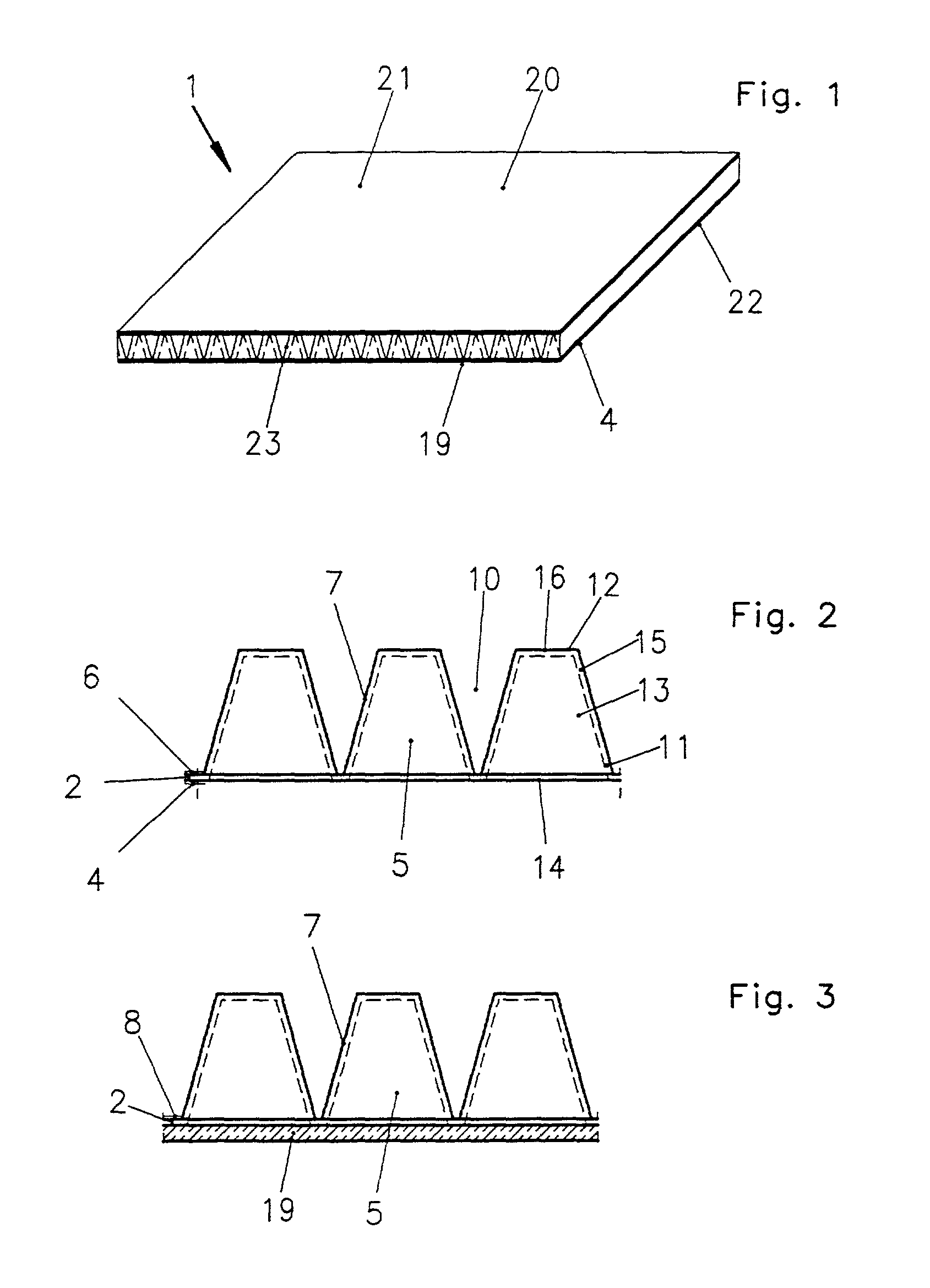
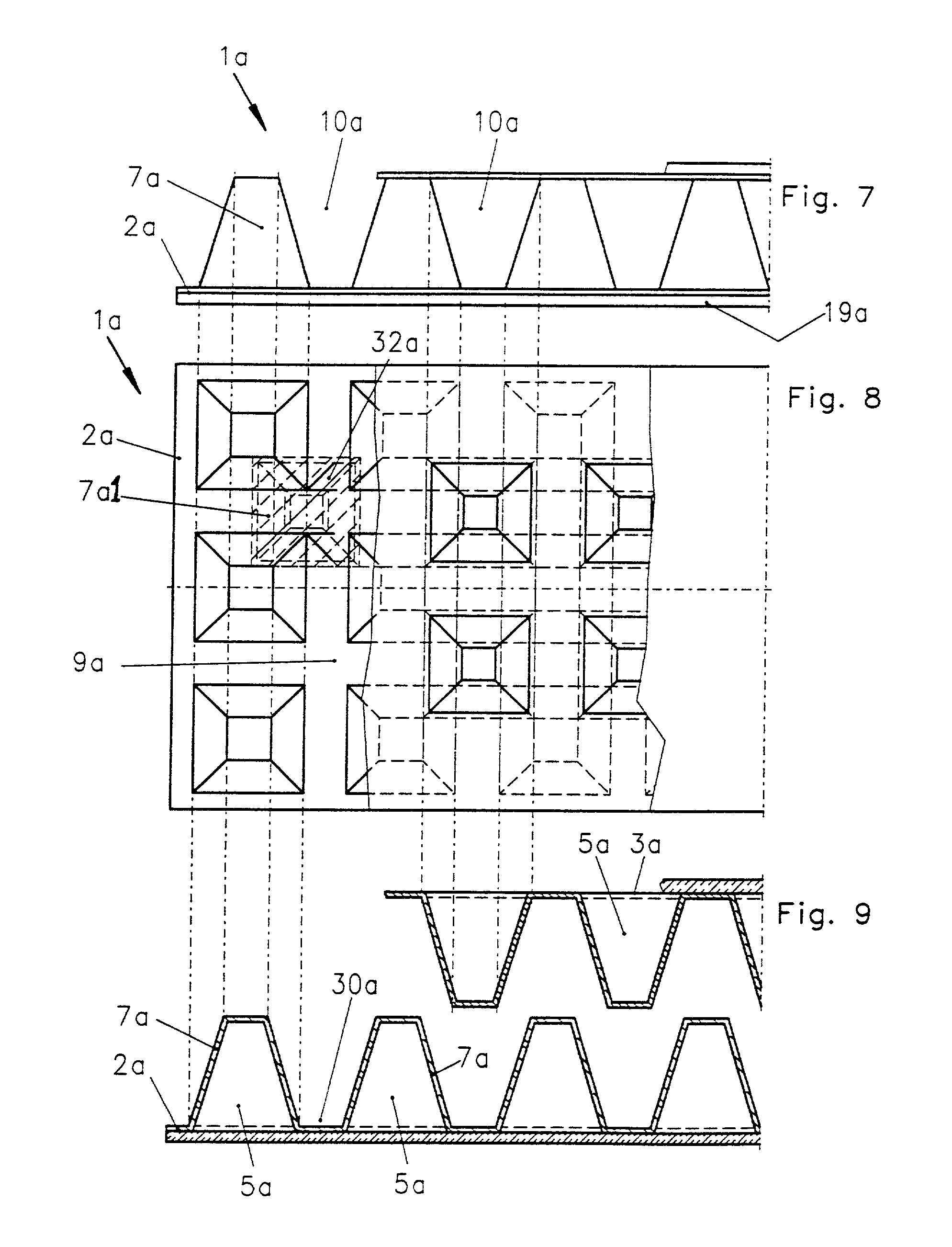
[0036] A multi-layered panel element 1 according to the invention, and particularly the embodiments shown in FIGS. 1 to 6, comprises a first profiled cup member layer 2 and a second similarly profiled cup member layer 3. Preferably, these two layers 2 and 3 are each configured the same as one another. In the present example embodiment this is the case, so the details of both layers will predominantly be discussed with reference to the layer 2 as shown in FIGS. 2 and 3, whereby it is understood that the layer 3 has the same features.

[0037] The two layers 2 and 3 each comprise depressions or recesses 5 that form hollow concave bowls or cups on one side 4 of the respective layer, and corresponding protrusions 7 on the other side 6 of the respective layer, whereby these protrusions 5 form the outer or convex side of the respective cups. Along the edges or rims 8 thereof, and in areas between the depressions 5 and between the protrusions 7, the two layers 2 and 3 include flat planar area...


PUM

PropertyMeasurementUnit
Shapeaaaaaaaaaa
Surface areaaaaaaaaaaa
Thermoplasticityaaaaaaaaaa

Abstract

A form-stable panel element, such as an automobile ceiling headliner, includes two layers of pyramid frustum-shaped cups that are intermeshed with each other, and two cover layers that close and seal hollow chambers in each of the cups. Each chamber is filled with a filler material that may be a loose mixed granulate of waste or recycled polymer. All of the layers are thermally fused and laminated integrally together. The panel element may be molded into a three-dimensional contour. The panel element is strong, lightweight, stiff against bending, incorporates waste or recycled materials, and provides good noise damping.

Description

PRIORITY CLAIM[0001] This application is based on and claims the priority under 35 U.S.C. .sctn.119 of German Utility Model Application 200 01 729.2, filed on Feb. 1, 2000, the entire disclosure of which is incorporated herein by reference.[0002] The invention relates to a multi-layered panel element that is substantially rigid and form-stable, yet light in weight, and suitable for use especially for trim and finish components, such as ceiling headliners, package shelves, trunk floors, wall panels, or the like within motor vehicles, or similar components of furniture and furnishings as well as wall panels or dividers for residential and commercial building construction. The sandwich-form panel element has a high bending stiffness and bending strength, and can be fabricated with simple processes. The invention further relates to an apparatus for manufacturing such a panel element.BACKGROUND INFORMATION[0003] Various types of lightweight panel elements are known in the prior art. One ...

Claims


Application Information

Patent Timeline
IPC IPC(8): B29C43/20B29C51/02B29C51/08B29C51/26B60R13/01E04C2/34
CPCB29C33/0022B29C43/00B29C43/203B29C43/40B29C51/02B29C51/082B29C51/261B29C2043/023B29C2043/3416B29C2043/3623B29C2791/001B29K2105/06B29L2031/3011B29L2031/3041B60R13/01E04C2/3405E04C2002/3422E04C2002/3427E04C2002/3472E04C2002/3494
Inventor SPENGLER, ERNST MAXIMILIAN
Owner R S TECHN
Learn More