Method, and apparatus for simulating a system using an object oriented language

a technology of object oriented language and system, applied in the direction of instrumentation, program control, cad circuit design, etc., can solve the problems of troublesome work, large number of statements to be rewritten, and the replacement of circuit modules in the system is a laborious and laborious process, so as to achieve the effect of easy replacement of circuit modules

Inactive Publication Date: 2001-09-13
NEC ELECTRONICS CORP
View PDF4 Cites 13 Cited by
  • Summary
  • Abstract
  • Description
  • Claims
  • Application Information

AI Technical Summary

Benefits of technology

[0023] The present invention is characterized by the statements of the simulation model of the system. The present invention uses the object oriented language to describe the system. Therefore, the properties of the circuit modules can be prepared as the class library. A user (designer) can use the inheritance of the properties when describing the circuit modules. The present invention provides the following advantages: (1) it is easy to replace the circuit module, and the connections between the circuit modules are automatically checked, (2) the configuration for displaying the information is commonly used, (3) the configuration for controlling the simulation is commonly used, and (4) it is automatically checked whether the statements of the circuit interfaces are sufficient.

Problems solved by technology

However, there are some problems in the application of this software simulation to SOCs such as LSIs (Large Scale Integrations) having a high integration degree.
Thus, when combining the circuit modules to produce the system, the designers must do the troublesome work to check the connections between the modules.
There is the problem that, to change the described connections, a number of portions in the statements must be rewritten.
It therefore requires much labor to replace a circuit module in the system.
The reference, however, does not disclose a specific means for applying the simulation method, or the method for describing the modules to a large scale system in which a plurality of various types of circuit modules are connected.
The simulation method and the method for describing the modules, however, do not make use of the advantages of the object oriented language.
Therefore, there remains a problem similar to that of the HDL in the recycling of the modules and the connections between the modules.
/ / Therefore, the compiler outputs an error.

Method used


Image

  • Method, and apparatus for simulating a system using an object oriented language
  • Method, and apparatus for simulating a system using an object oriented language
  • Method, and apparatus for simulating a system using an object oriented language

Examples


Embodiment Construction

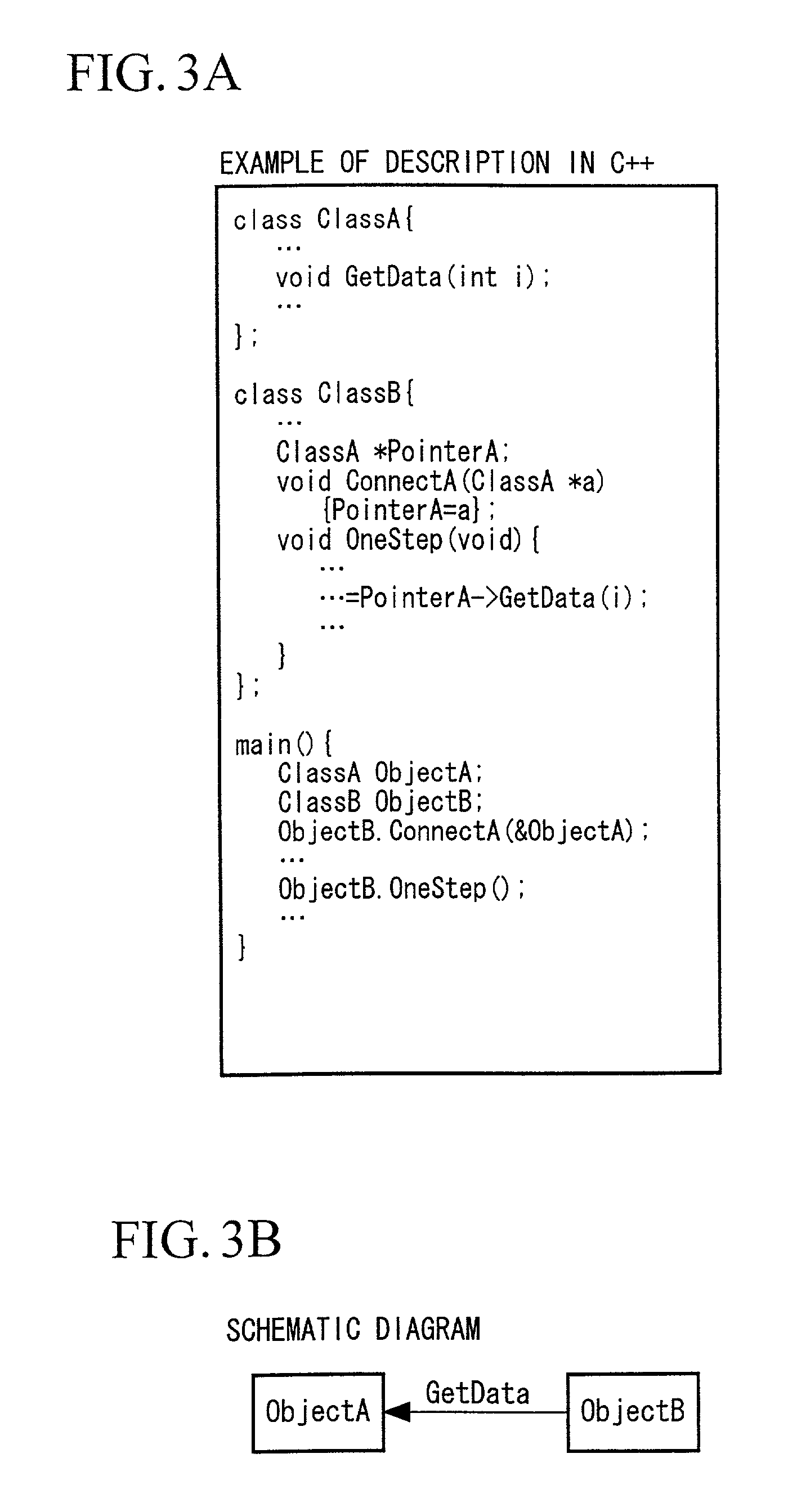
++ class ClassA { . . . void GetData (int I); . . . }; class ClassB{ . . . ClassA *PointerA; void ConnectA (ClassA *a) {Pointer A=a}; void OneStep (void) { . . . . . . = PointerA->GetData(I); . . . } }; main () { ClassA ObjectA; ClassB ObjectB; ObjectB.ConnectA (&ObjectA); . . . ObjectB.OneStep(); . . . }

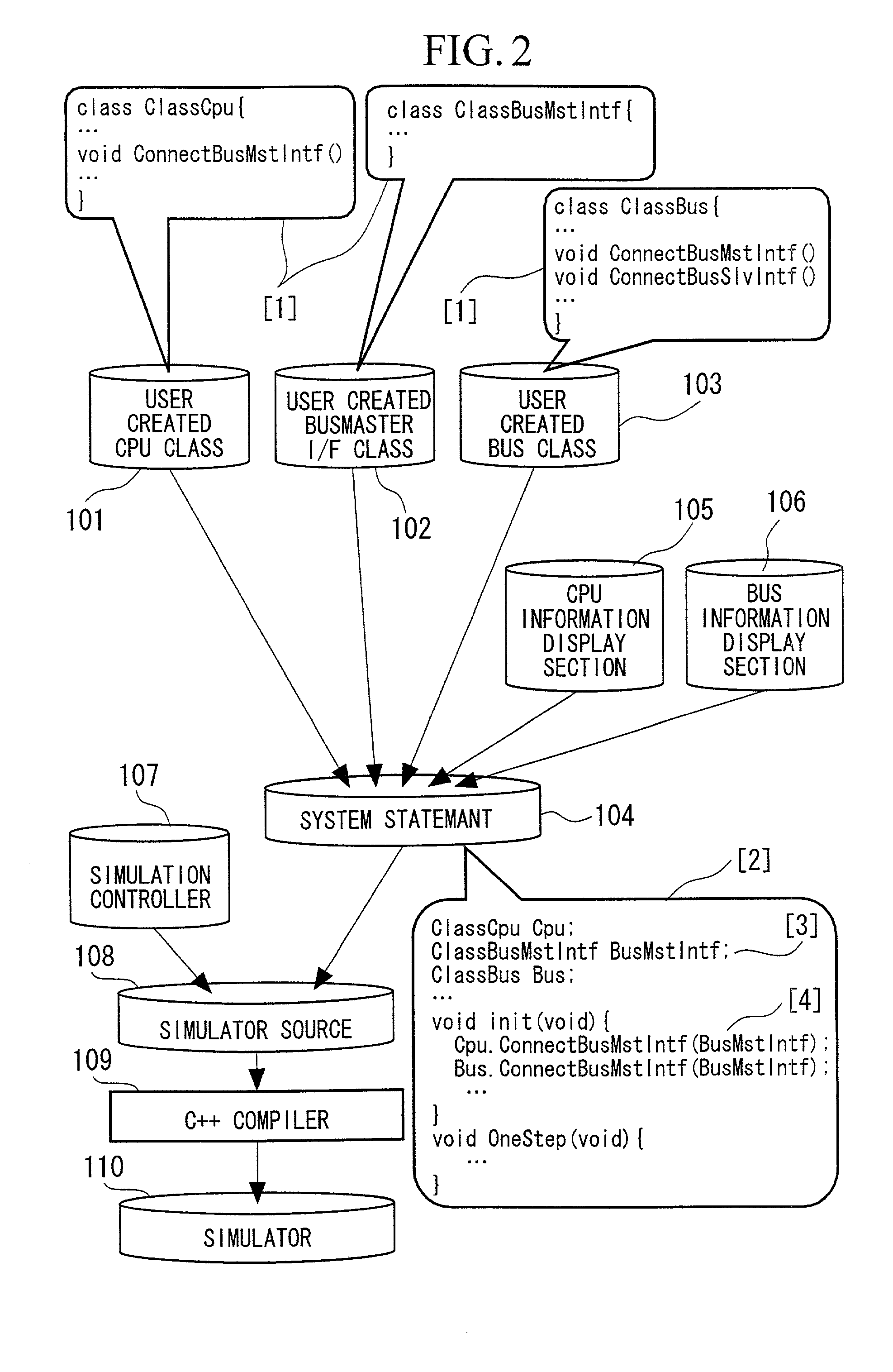
[0051] (C) Next, an information display section of the circuit is incorporated. In the prior certifications with simulations, it was necessary to know how the CPU and the bus operate, for example, to know the portion of software the CPU is executing, the variables of the software operating in the CPU, the share of the bus, a master which is using the bus, or the like. The statement of the process for displaying those information is added to the system statement. In FIG. 2, the statement for displaying the information of the bus prepared in advance in a library, and the statement for displaying the information of the bus may be modified if necessary, and are incorporated at appropria...


PUM


Abstract

The simulation method of the present invention for simulating a system having a plurality of circuit modules using software, comprises the steps of: using an object oriented language; preparing a plurality of circuit base classes, which describe base circuit modules as classes, as a library; describing the circuit modules, to be simulated, as classes by inheriting the circuit base classes prepared as the library; and describing the system, to be simulated, by combining the circuit modules described as the classes.

Description

[0001] 1. Field of the Invention[0002] The present invention relates to a method, an apparatus, and a storage medium for simulating a system using an object oriented language suitable for the simulation of a large scale system such as an SOC (System On a Chip), which includes a plurality of circuit modules, by means of software.[0003] 2. Description of the Related Art[0004] There are conventional software simulators using the HDL (Hardware Description Language) for designing a system. Table 1 shows the examples of statements of a circuit model in the HDL, and FIG. 1 is a schematic diagram corresponding to the statement examples of Table 1. Data is input to or output from the circuit module described in the HDL through terminals. The communication between the circuit modules is made by connecting signal lines to the terminals. For example, as shown in FIG. 1 , when a circuit module C includes circuit modules A and B, a terminal a1 of the circuit module A is connected to a terminal b1...

Claims


Application Information

Patent Timeline
Patent Type & Authority Applications(United States)
IPC IPC(8): G06F9/44G06F17/50
CPCG06F17/5022G06F30/33
Inventor RYU, HIROSHIKATOH, YUSUKE
Owner NEC ELECTRONICS CORP
Why Eureka
Try Eureka