Directly actuated injection valve

Inactive Publication Date: 2001-10-25
WESTPORT FUEL SYST CANADA INC
View PDF0 Cites 34 Cited by
  • Summary
  • Abstract
  • Description
  • Claims
  • Application Information

AI Technical Summary

Benefits of technology

0115] an apparatus that permits the use of a control strategy that can throttle fuel flow and reduce valve seat wear. The ability to control the lift displacement permits reduced injection at lower loads and reduced pre-mixed burning. For example, using a magnetostrictive or piezoelectric actuator, the valve member movement can be controlled between about 10% and 100%. For lower load conditions it is important to be able to reduce the flow of fuel into the combustion chamber, since excess fuel may not be combusted, resulting in lower operating efficiency and higher emissions.
0116] improved manufacturability is made possible by the use of axis

Problems solved by technology

Direct injection at high pressures presents several challenges.
The use of high-pressure fuels for direct injection results in high fuel pressures existing within the injection valve or injector.
Moreover, compared to low-pressure systems, higher forces are needed to open or close the injection valve.
For example, for a needle valve that employs an inwardly opening valve needle, when the needle is in the open position it may be subjected to high forces from the pressurized fuel.
Conversely, with an outward opening injection valve, a high amount of force is required to keep the valve closed against the high fuel pressure within the injection valve body.
Additionally, there is only a small window of time during which the fuel can be injected.
However, in the context of a conventional gaseous injection valve, hydraulic operation presents several drawbacks, including:
increased bulkiness of the injection valve assembly because of the additional hardware requirements; and
delayed response of the system caused by time delays associated with the dynamic flow of the hydraulic fluid, the actuation of the electronic hydraulic valve hardware and the movement of the needle that controls gas flow from the injection valve.
Moreover, the degree of controlla

Method used


Image

  • Directly actuated injection valve
  • Directly actuated injection valve
  • Directly actuated injection valve

Examples


Embodiment Construction

)

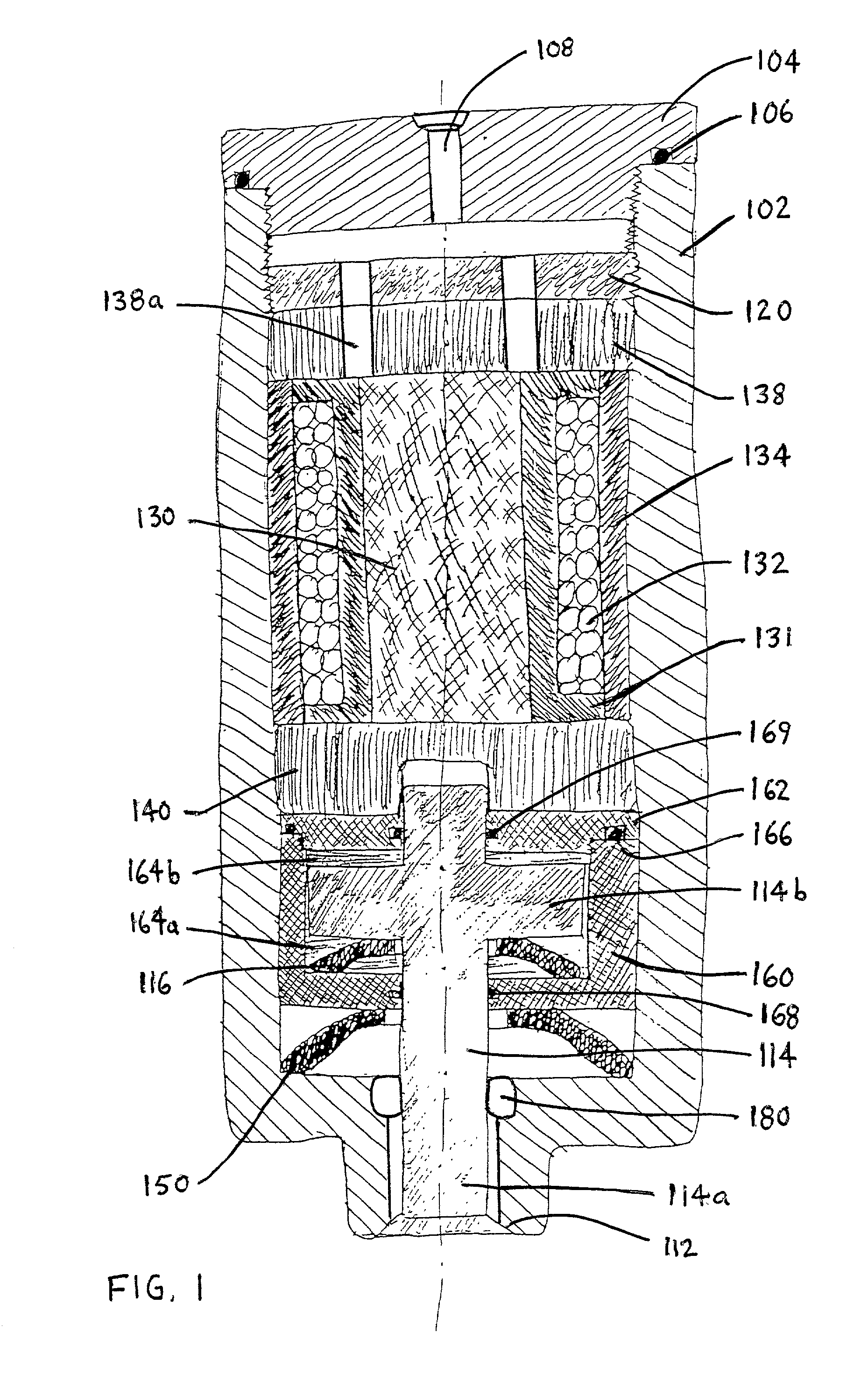
[0069] FIGS. 1 and 3 show two different preferred embodiments of an outward opening directly actuated fuel injection valve for internal combustion engines. Opposed to a needle valve, which employs a needle that is retracted into the valve body to open the valve, an outward opening injection valve extends a valve member outward and away from the valve body to open the valve. To open an outward opening fuel injection valve for injecting fuel into an engine, a valve member is moved away from a valve seat and towards the combustion chamber.

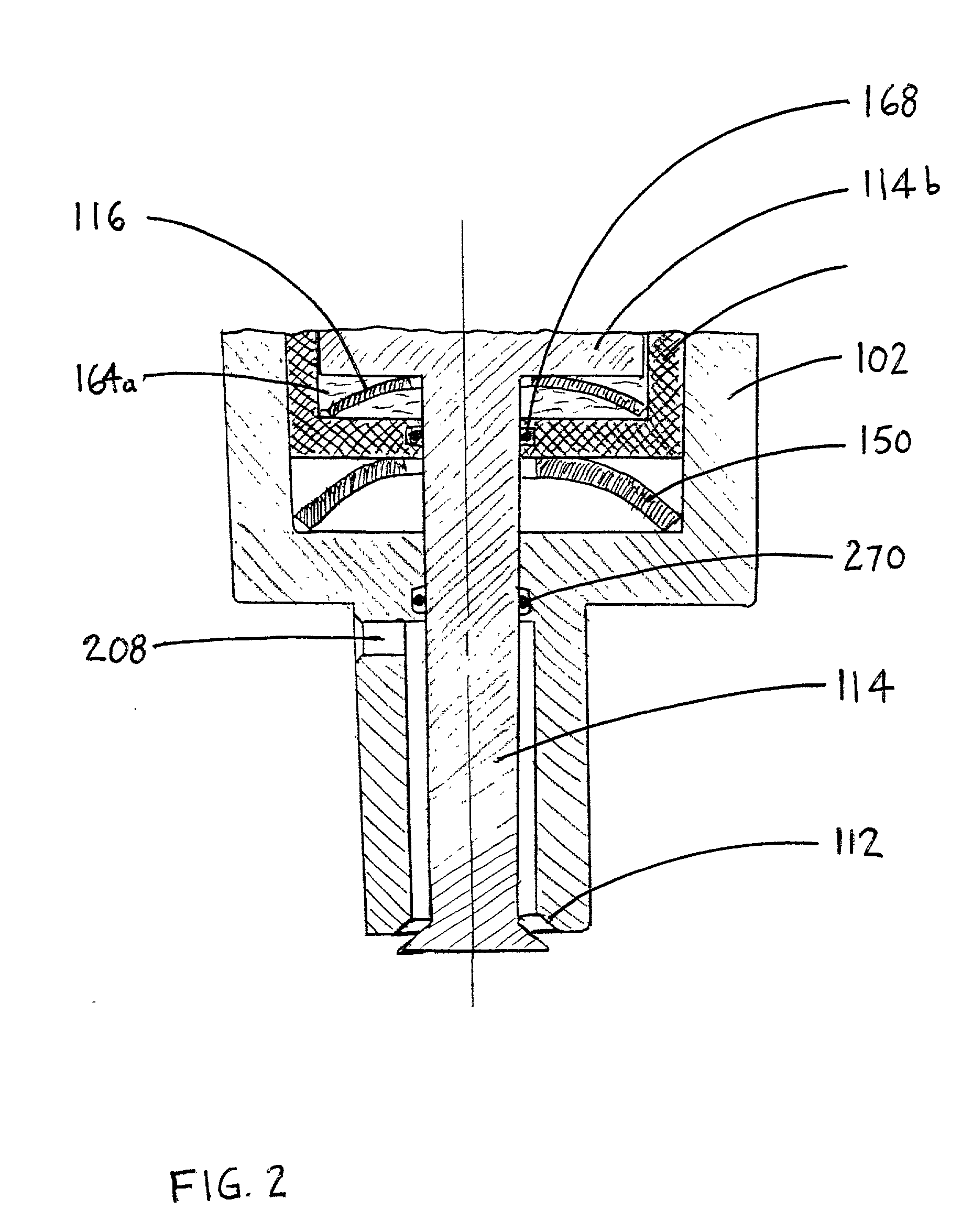
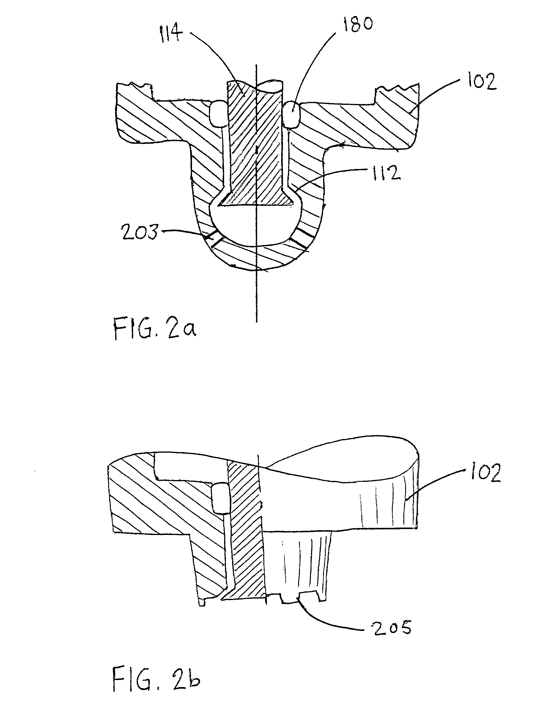
[0070] Referring to FIGS. 1 and 2, injection valve 100 includes elongated valve housing 102 that cooperates with valve cap 104 to provide a fluidly sealed valve body. Seal 106 may be employed to ensure that the assembled valve body is fluid-tight. Valve cap 104 comprises inlet port 108 through which fuel enters the valve body. Valve housing 102 further comprises valve seat 112, which is better shown in FIG. 2, which shows an injection valve in the op...


PUM


Abstract

A directly actuated injection valve comprises a hollow valve housing, a valve member disposed within the hollow interior, a biasing mechanism, an actuator assembly and a hydraulic link assembly. The valve member is movable between a closed position and an open position for governing the flow of fuel into the combustion chamber of an internal combustion engine. The biasing mechanism, preferably a spring, biases the valve member in the closed position. The actuator assembly generates an opening force that acts against the valve spring to open the valve. The hydraulic link assembly is interposed between the valve member and the valve spring and the actuator assembly. The hydraulic link assembly transmits respective closing and opening forces to the valve member. The hydraulic link preferably comprises a piston disposed within a cylinder that is filled with a hydraulic fluid. The opening and closing forces are transmitted through a thickness of the hydraulic fluid that is trapped between the planar surfaces of the piston and the head and base of the hydraulic cylinder.

Description

CROSS-REFERENCE TO RELATED APPLICATION(S)[0001] This application is a continuation-in-part of U.S. patent application Ser. No. 09 / 522,130 filed Mar. 9, 2000, entitled "Directly Actuated Injection Valve", now U.S. Pat. No. ______ issued ______. The '130 application relates to and claims priority benefits from U.S. Provisional Patent Application Ser. No. 60 / 159,791 filed Oct. 15, 1999, entitled "Directly Actuated Injector". The '130 application and the '791 application are each incorporated herein by reference in their entirety.[0002] The present invention relates generally to high pressure fuel injection valves or injectors for internal combustion engines, and, more specifically, to an injection valve that is directly controllable by a position actuating material (such as, for example, a piezoelectric or magnetostrictive material) and which includes a passive hydraulic link.[0003] Direct injection of a gaseous fuel into the combustion chamber of an internal combustion engine is desir...

Claims


Application Information

Patent Timeline
IPC IPC(8): F02D41/20F02M21/02F02M51/00F02M47/00F02M47/04F02M51/06F02M61/08F02M61/10F02M61/16F02M63/00
CPCF02B2275/14F02D41/20F02D41/2096F02D2041/2037F02M51/005F02M51/0603F02M51/0607F02M61/08F02M61/10F02M61/166F02M61/167F02M2200/30F02M2200/304F02M2200/507Y02T10/123Y02T10/32F02M21/0269F02M21/0254Y02T10/12Y02T10/30
Inventor WELCH, ALAN B.RAHARDJA, IRAWANHEBBES, MIKE
Owner WESTPORT FUEL SYST CANADA INC
Why Eureka
Try Eureka