Echo and crosstalk cancellation

a crosstalk and echo technology, applied in the field of cancellation of echo and crosstalk, can solve the problems of large and complex system, inconvenient operation, and inability to meet, and achieve the effect of reducing the complexity of the system

Inactive Publication Date: 2001-11-01
AVAGO TECH WIRELESS IP SINGAPORE PTE
View PDF5 Cites 69 Cited by
  • Summary
  • Abstract
  • Description
  • Claims
  • Application Information

AI Technical Summary

Benefits of technology

[0006] Heretofore, the approach to deal with these interference signals has been to generate a replica signal to the noise source and to subtract it from the received signal. This is possible because the four near transmit signals are known, and the three far transmit signals can be deduced. The corresponding noise signal due to any given transmit signal can be approximated at the receiver using the transmit signal as the starting point. This is usually done using an adaptive finite impulse response filter ("adaptive FIR filter" or "AFIR"), one for each of the noise sources, and the input to each AFIR is the corresponding transmit signal. The coefficients of each AFIR are adapted to minimise the difference (MSE--mean square error) between the received signal plus the total noise signal less the output of the AFIR (which is an approximation to the noise signal corresponding to that transmit signal).
[0009] It is known that though the span of an echo canceller required to cancel echo for a given system may need to be very large it is usual that not all of the taps are necessary. The difficulty lies in identifying which taps are necessary and which are not as this will vary from cable to cable and indeed may vary from time to time. This is known to also be a problem in acoustic echo cancellers. A method of tackling this problem has been proposed in WO99 / 46867 (Broadcom, Gigabit Ethernet Transceiver), in which after the echo canceller has been trained a certain number of taps are switched off. A method is described to determine which taps are important and which are not making a significant contribution to noise reduction. This method has the advantage of reducing the power dissipation of the circuit, though no reduction in area is achieved (in fact area appears to be increased).
[0010] The invention is directed towards providing improved echo and crosstalk cancellation.

Problems solved by technology

These mismatches may occur at junctions and patch cords.
Because there are four pairs of unshielded cable there is the additional problem of crosstalk.
A problem with the above approach is that it is a very large and complex system and is expensive in terms of computational complexity, silicon area, and power consumption.
The difficulty lies in identifying which taps are necessary and which are not as this will vary from cable to cable and indeed may vary from time to time.
This is known to also be a problem in acoustic echo cancellers.

Method used


Image

  • Echo and crosstalk cancellation
  • Echo and crosstalk cancellation
  • Echo and crosstalk cancellation

Examples


Embodiment Construction

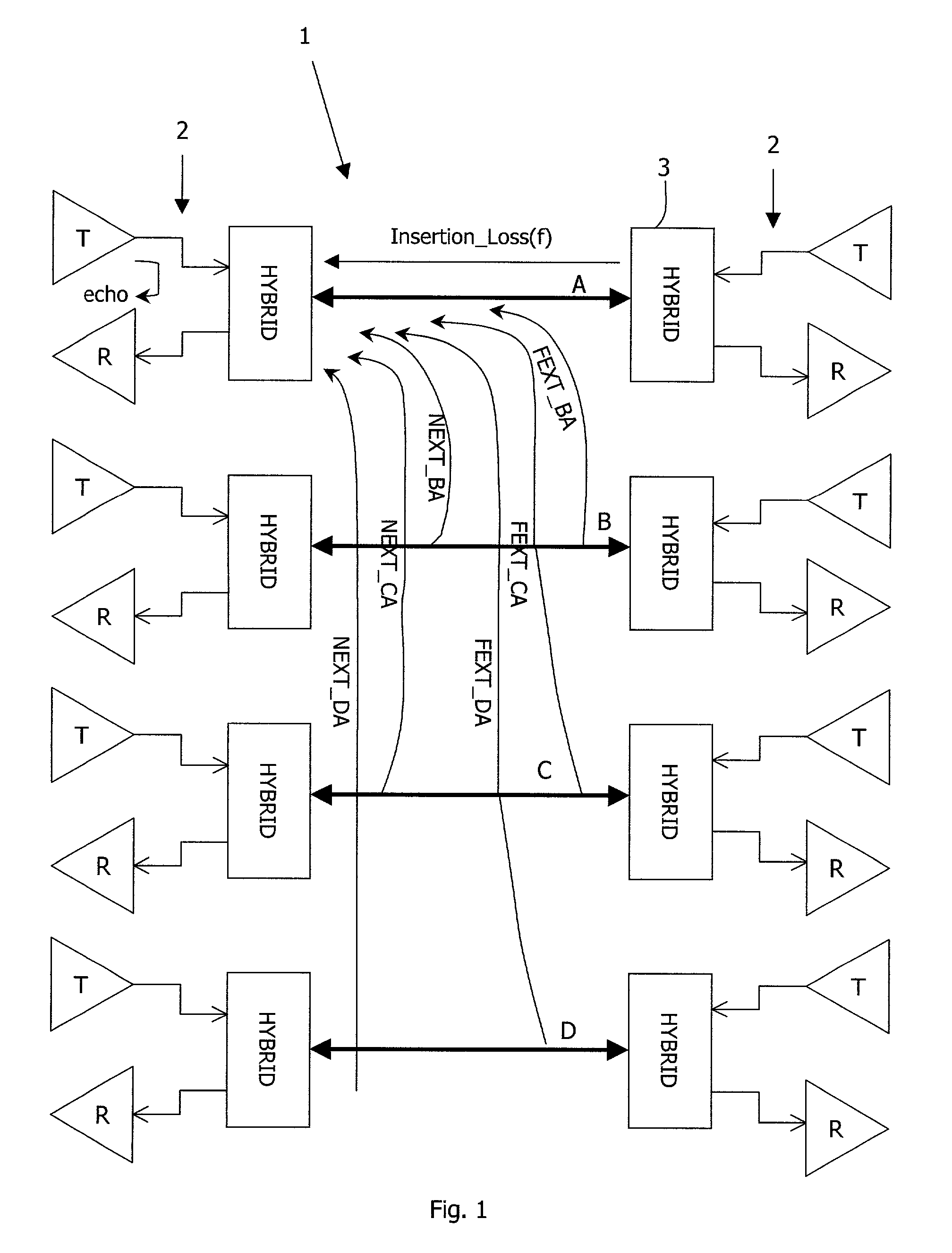
[0038] Referring to FIG. 1 a Gigabit system 1 comprises four cable pair channels A, B, C, and D and a transceiver 2 at each end. Each transceiver 2, at a high level, comprises a transmitter T, a receiver R, and a hybrid 3 physically connected to each cable A, B, C, and D. The echo and crosstalk sources for the left side transceiver 2 for cable pair A are illustrated by arrows. There are three FEXT interferances FEXT_BA, FEXT_CA, and FEXT_DA, three NEXT interferances NEXT_BA, NEXT_CA, and NEXT_DA, and finally, there is an echo in the receiver R from the associated transmitter T and from points of impedance mis-match along the cable.

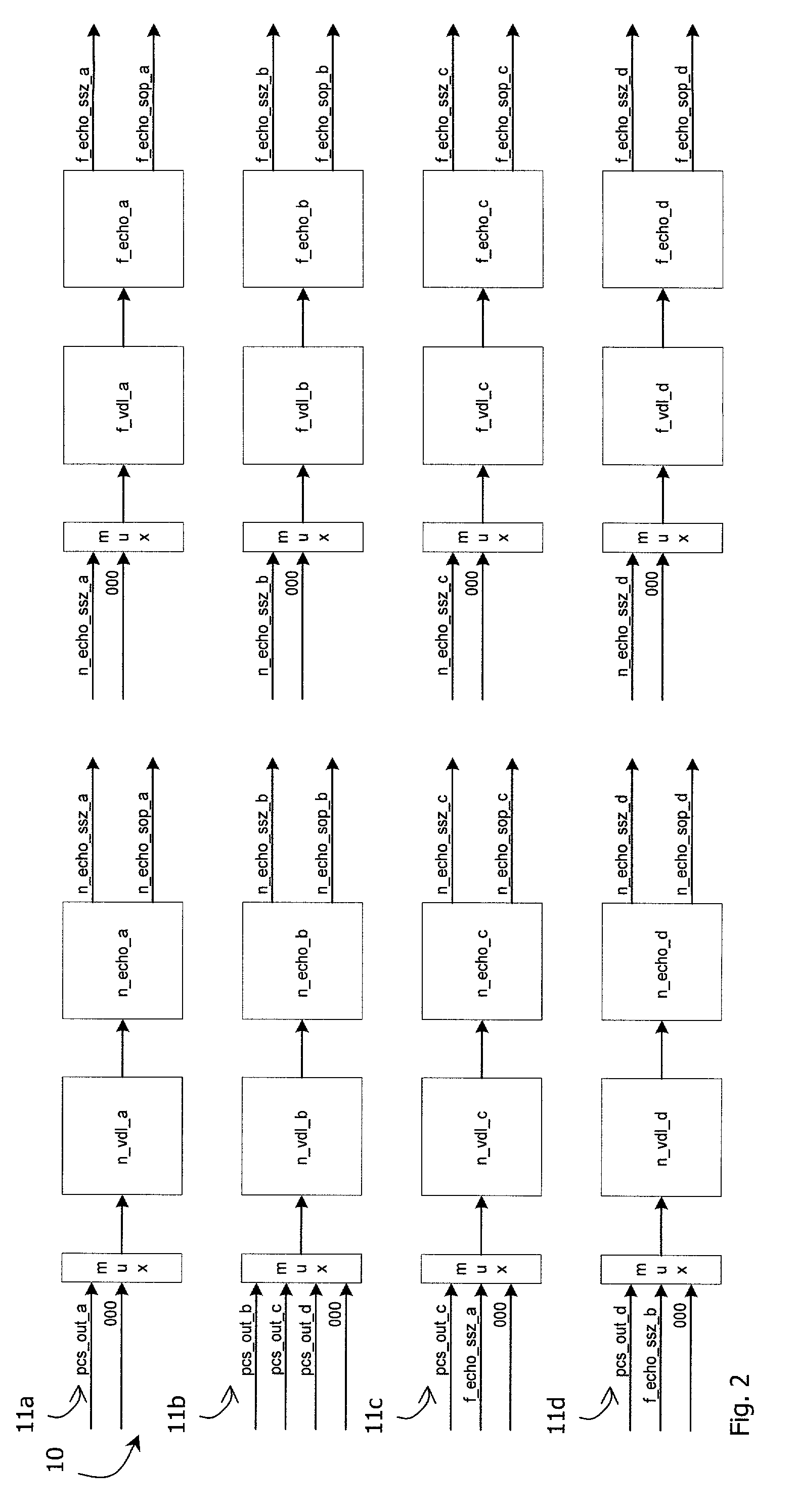
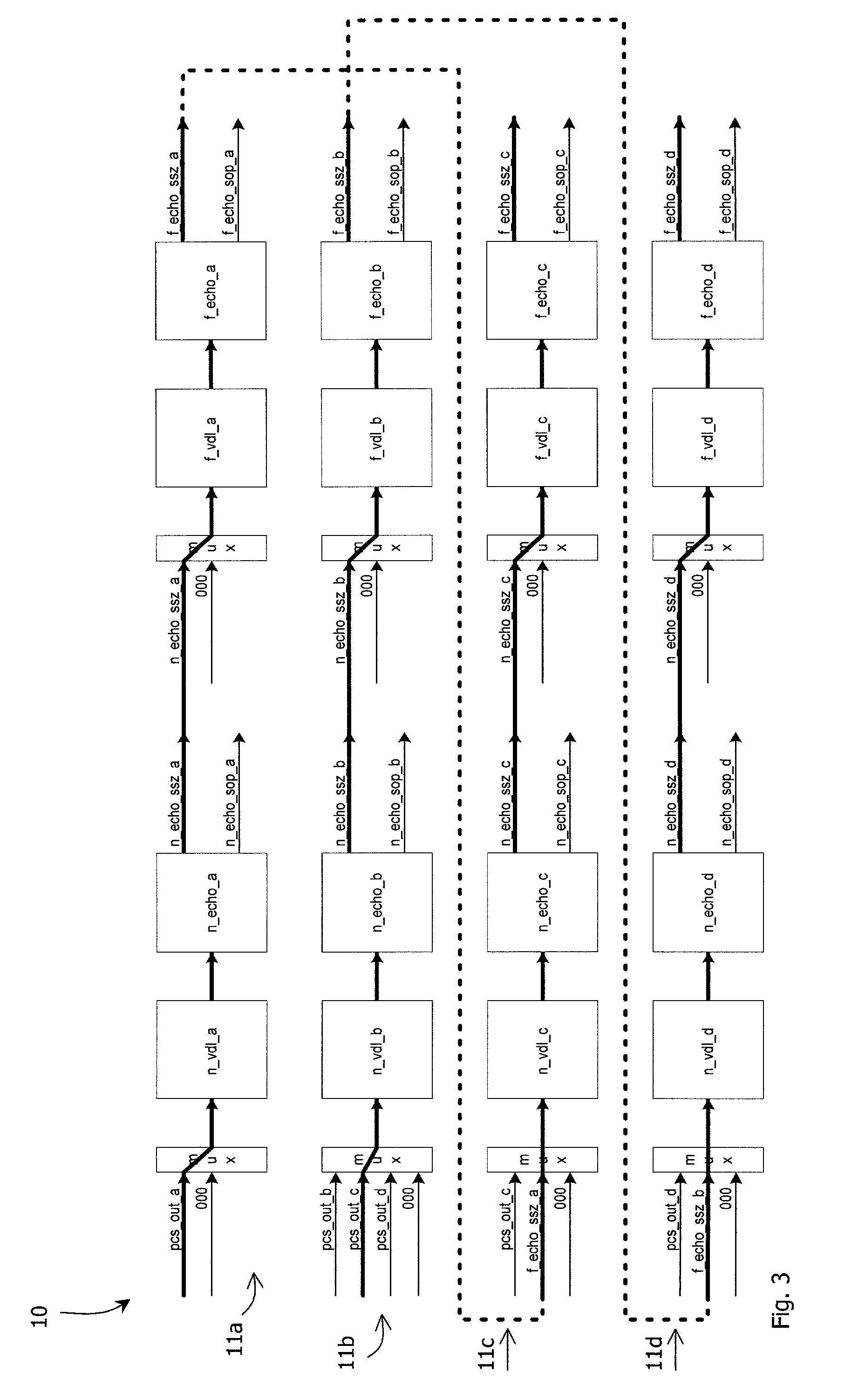
[0039] The invention provides an echo and NEXT cancellation system for each transceiver 2. Each cancellation system comprises an echo canceller for dealing with echo in all of the four cable pairs, and a NEXT canceller for dealing with the twelve sources of NEXT. The echo canceller is illustrated, the structure and principles of operation for the NEXT canc...


PUM


Abstract

A cancellation system comprises a channel circuit (11) for each noise source, such as echo in a particular cable pair. There are only eighty taps per channel, in two blocks (n_echo_a, f_echo_a). Each block is preceded by a variable delay line comprising blocks of registers cascaded so that a delay value of 0 to 40 clock cycles can be chosen. The delay value is determined by determining an optimum position for each tap block. This is achieved by determining a maximum coefficient sum for a number of windows. Taps from other channels are used during training, so that there is a total of 160 taps for each channel during training to enable the optimum positions to be determined.

Description

[0001] 1. Field of the Invention[0002] The invention relates to cancellation of echo and crosstalk in high-speed networks such as 1 Gb / s networks.[0003] 2. Prior Art Discussion[0004] Taking the example of 1 Gb / s networks, there are typically four cable pair channels, say A, B, C, and D. Each pair is used for both transmit and receive. Due to mismatches in the cable impedance there is an echo returned to the receiver. These mismatches may occur at junctions and patch cords. In addition, the transceiver hybrid only partially attenuates the locally transmitted signal. This combination is known as the echo signal and it appears as a noise source to the receiver.[0005] Because there are four pairs of unshielded cable there is the additional problem of crosstalk. The other three transmitters (at the same end as the receiver) all generate interference signals known as near-end crosstalk (NEXT). Furthermore, the three transmitters at the far end generate interference signals known as far-en...

Claims


Application Information

Patent Timeline
Patent Type & Authority Applications(United States)
IPC IPC(8): H04B3/23H04B3/32
CPCH04B3/23
Inventor CURRAN, PHILIPMOLINA, ALBERTMURRAY, BRIANMURRAY, CARL
Owner AVAGO TECH WIRELESS IP SINGAPORE PTE
Why Eureka
Try Eureka