Electro-optical device
a technology of optical devices and optical components, applied in non-linear optics, instruments, optics, etc., can solve problems such as signal delay and increase in manufacturing steps
- Summary
- Abstract
- Description
- Claims
- Application Information
AI Technical Summary
Problems solved by technology
Method used
Image
Examples
embodiment 1
[0076] [Embodiment 1]
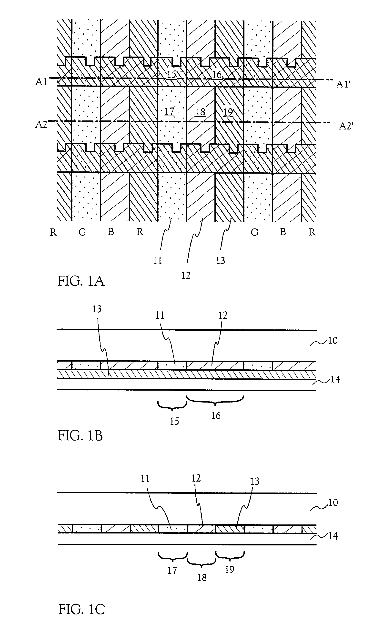
[0077] An embodiment of the present invention will be described hereinbelow with taking as an example a manufacturing of an opposing substrate which will be employed for an active matrix liquid crystal display device. FIGS. 1A-1C show an opposing substrate having colored layers which are formed according to the present invention.
[0078] First, as a substrate 10 having light translucent property, a glass substrate such as barium borosilicate glass or aluminum borosilicate, represented by such as Corning #7059 glass and #1737 glass is prepared. In addition to the above, a light translucent type substrate such as a quartz substrate and a plastic substrate may also be used.
[0079] Then, an organic photosensitive material (CGY-S705C: COLOR MOSAIC, manufactured by Fuji Film Olin Co.) is applied onto the opposing substrate 10, and the organic photosensitive material is patterned into stripe shape as shown in FIG. 1A by a photolithography method to form the green-colored ...
embodiment 2
[0089] [Embodiment 2]
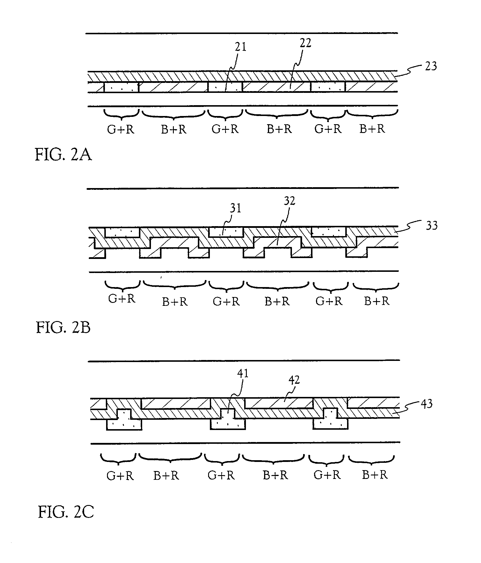
[0090] In Embodiment 1, an example is shown in which the green-colored layer (G) 11, the blue-colored layer (B) 12, and the red-colored layer (R) 13 are formed in sequence. However, in this embodiment, a description will be made hereinbelow of an example of forming the respective colored layers in an order different from that in Embodiment 1. Note that, except the order of forming the respective colored layers, the other manufacturing steps are the same with that in Embodiment 1, thereby only different points will be described.
[0091] A structure shown in FIG. 2A may be taken as a first example. FIG. 2A shows an example in which a colored layer (R) 23 is first formed, and then, a colored layer (B) 22 and a colored layer (G) 21 are laminated thereon. Note that FIG. 2A corresponds to a sectional view taken along the dash line of A1-A1' of FIG. 1A.
[0092] Further, a structure shown in FIG. 2B may be employed as a second example. FIG. 2B is an example in which a color...
embodiment 3
[0094] [Embodiment 3]
[0095] In this embodiment, a description will be made of a manufacturing method of a device substrate (also referred to as an active matrix substrate) which is stuck with an opposing substrate obtained in Embodiment 1 or Embodiment 2. Here, a method of simultaneously forming, on the same substrate, a pixel portion and TFTs (n-channel TFT and p-channel TFT) of a driver circuit formed in the periphery of the pixel portion, is described in detail.
[0096] First, in this embodiment, a substrate 100 is used, which is made from glass, such as barium borosilicate glass or aluminum borosilicate, represented by such as Corning #7059 glass and #1737. Note that, as the substrate 100, a quartz substrate, or a silicon substrate, a metal substrate, or a stainless substrate, on which an insulating film is formed, may be used as the replace. A plastic substrate having heat resistance to a process temperature of this embodiment may also be used.
[0097] Then, as shown in FIG. 5A, a ...
PUM
| Property | Measurement | Unit |
|---|---|---|
| wavelength | aaaaa | aaaaa |
| wave length | aaaaa | aaaaa |
| width | aaaaa | aaaaa |
Abstract
Description
Claims
Application Information
 - R&D
- Intellectual Property
- Life Sciences
- Materials
- Tech Scout
- Unparalleled Data Quality
- Higher Quality Content
- 60% Fewer Hallucinations
Browse by: Latest US Patents, China's latest patents, Technical Efficacy Thesaurus, Application Domain, Technology Topic, Popular Technical Reports.
© 2025 PatSnap. All rights reserved.Legal|Privacy policy|Modern Slavery Act Transparency Statement|Sitemap|About US| Contact US: help@patsnap.com


